| Last Modified: 08-28-2024 | 6.11:8.1.0 | Doc ID: RM100000000VIF1 |
| Model Year Start: 2016 | Model: Sienna | Prod Date Range: [12/2015 - 08/2016] |
| Title: 2GR-FE INTAKE / EXHAUST: EXHAUST PIPE(for 2WD): INSTALLATION; 2016 MY Sienna [12/2015 - 08/2016] | ||
INSTALLATION
PROCEDURE
1. INSTALL NO. 2 OXYGEN SENSOR (for Bank 2 Sensor 2)
|
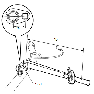
(a) Using SST, install the No. 2 oxygen sensor (for bank 2 sensor 2) to the front exhaust pipe assembly. Text in Illustration
SST: 09224-00010 Torque: Specified tightening torque : 44 N·m {449 kgf·cm, 32 ft·lbf} NOTICE: If a component has been dropped or subjected to a strong impact, replace No. 2 oxygen sensor (for bank 2 sensor 2). HINT:
|
|
![2016 MY Sienna [12/2015 - 08/2016]; INTRODUCTION: REPAIR INSTRUCTION: PRECAUTION](/t3Portal/stylegraphics/info.gif)
2. INSTALL OXYGEN SENSOR (for Bank 1 Sensor 2)
|
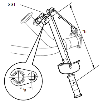
(a) Using SST, install the oxygen sensor (for bank 1 sensor 2) to the front exhaust pipe assembly. Text in Illustration
SST: 09224-00010 Torque: Specified tightening torque : 44 N·m {449 kgf·cm, 32 ft·lbf} NOTICE: If a component has been dropped or subjected to a strong impact, replace oxygen sensor (for bank 1 sensor 2). HINT:
|
|
3. INSTALL FRONT EXHAUST PIPE ASSEMBLY
(a) Install 2 new gaskets to the front exhaust pipe assembly.
(b) Install the front exhaust pipe assembly to the exhaust manifold sub-assembly LH (TWC: front catalyst) and exhaust manifold sub-assembly RH (TWC: front catalyst) with 4 new nuts.
Torque:
62 N·m {632 kgf·cm, 46 ft·lbf}
(c) Connect the exhaust pipe clamp to the No. 1 exhaust pipe support bracket and tighten the bolt.
Torque:
21 N·m {214 kgf·cm, 15 ft·lbf}
(d) Engage the 6 clamps to connect the oxygen sensor (for bank 2 sensor 2) wire to the 2 wire harness clamp brackets.
(e) Connect the oxygen sensor (for bank 2 sensor 2) connector.
(f) Pass the connector through the hole to the inside of the vehicle and install the grommet of the oxygen sensor (for bank 1 sensor 2) wire.
(g) Connect the oxygen sensor (for bank 1 sensor 2) connector.
4. INSTALL EXHAUST PIPE DAMPER
(a) Install the exhaust pipe damper to the center No. 2 exhaust pipe sub-assembly with the 2 new bolts.
Torque:
19 N·m {194 kgf·cm, 14 ft·lbf}
5. INSTALL CENTER EXHAUST PIPE ASSEMBLY
(a) Inspect the free length.
|
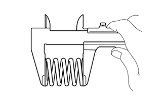
(1) Using a vernier caliper, measure the free length of the compression spring. Free Length of Compression Spring:
If the length is not as specified, replace the compression spring. |
|
|
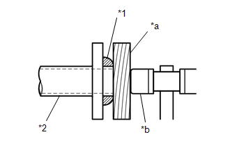
(b) Using a plastic hammer and a wooden block, tap in a new gasket until its surface is flush with the center No. 2 exhaust pipe sub-assembly. Text in Illustration
NOTICE:
|
|
|
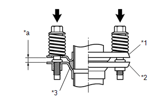
(c) Install the center exhaust pipe sub-assembly (TWC: rear catalyst) to the center No. 2 exhaust pipe sub-assembly with the 2 compression springs and 2 bolts. Text in Illustration
Torque: 43 N·m {438 kgf·cm, 32 ft·lbf} NOTICE: After the installation, check that the gaps between the flanges of the center exhaust pipe sub-assembly (TWC: rear catalyst) and center No. 2 exhaust pipe sub-assembly are consistent front-to-rear and left-to-right. |
|
(d) Inspect the free length.
|
(1) Using a vernier caliper, measure the free length of the compression spring. Free Length of Compression Spring:
If the length is not as specified, replace the compression spring. |
|
|
(e) Using a plastic hammer and a wooden block, tap in a new gasket until its surface is flush with the front exhaust pipe assembly. Text in Illustration
NOTICE:
|
|
(f) Connect the 2 exhaust pipe supports to install the center exhaust pipe assembly to the vehicle.
|
(g) Install the center exhaust pipe assembly to the front exhaust pipe assembly with the 2 compression springs and 2 bolts. Text in Illustration
Torque: 43 N·m {438 kgf·cm, 32 ft·lbf} NOTICE: After the installation, check that the gaps between the flanges of the center exhaust pipe assembly and front exhaust pipe assembly are consistent front-to-rear and left-to-right. |
|
6. INSTALL TAIL EXHAUST PIPE ASSEMBLY
(a) Install a new gasket to the center exhaust pipe assembly.
(b) Connect the 3 exhaust pipe supports to install the tail exhaust pipe assembly to the vehicle.
(c) Install the tail exhaust pipe assembly to the center exhaust pipe assembly with 2 new bolts.
Torque:
43 N·m {438 kgf·cm, 32 ft·lbf}
7. INSTALL INSTRUMENT PANEL FINISH PANEL END LH
(a) Engage the 3 guides and install the instrument panel finish panel end LH.
(b) Install the clip.
8. INSPECT FOR EXHAUST GAS LEAK
|
|
|