| Last Modified: 08-28-2024 | 6.11:8.1.0 | Doc ID: RM100000000VIEV |
| Model Year Start: 2016 | Model: Sienna | Prod Date Range: [12/2015 - 08/2016] |
| Title: 2GR-FE INTAKE / EXHAUST: EXHAUST MANIFOLD: INSTALLATION; 2016 MY Sienna [12/2015 - 08/2016] | ||
INSTALLATION
PROCEDURE
1. INSTALL NO. 2 AIR FUEL RATIO SENSOR (for Bank 2 Sensor 1)
|
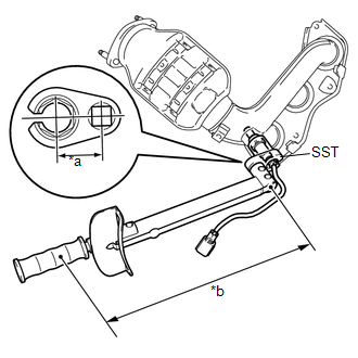
(a) Using SST, install the No. 2 air fuel ratio sensor (for Bank 2 Sensor 1) to the front exhaust manifold sub-assembly LH. Text in Illustration
SST: 09224-00010 Torque: Specified tightening torque : 44 N·m {449 kgf·cm, 32 ft·lbf} NOTICE: If a component has been dropped or subjected to a strong impact, replace No. 2 air fuel ratio sensor (for Bank 2 Sensor 1). HINT:
|
|
2. INSTALL EXHAUST MANIFOLD TO HEAD GASKET LH
(a) Install a new exhaust manifold to head gasket LH.
3. INSTALL EXHAUST MANIFOLD SUB-ASSEMBLY LH
|
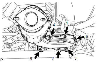
(a) Temporarily install the exhaust manifold sub-assembly LH with the 6 nuts. |
|
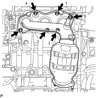
(b) Using a 12 mm deep socket wrench, tighten the 6 nuts in the order shown in the illustration.
Torque:
21 N·m {214 kgf·cm, 15 ft·lbf}
4. INSTALL NO. 2 EXHAUST MANIFOLD HEAT INSULATOR
|
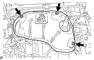
(a) Install the No. 2 exhaust manifold heat insulator, tightening the 3 bolts in the order shown in the illustration. Torque: 8.5 N·m {87 kgf·cm, 75 in·lbf} |
|
(b) Connect the air fuel ratio sensor (for Bank 2 Sensor 1) connector and engage the 2 harness clamps.
5. INSTALL NO. 2 MANIFOLD STAY
|
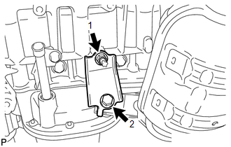
(a) Install the No. 2 manifold stay, tightening the bolt and nut in the order shown in the illustration. Torque: 34 N·m {347 kgf·cm, 25 ft·lbf} |
|
6. INSTALL NO. 2 OIL LEVEL DIPSTICK GUIDE
(a) Install a new O-ring to the No. 2 oil level dipstick guide.
(b) Apply a light coat of engine oil to the O-ring.
(c) Push in the No. 2 oil level dipstick guide end into the oil level dipstick guide.
(d) Install the No. 2 oil level dipstick guide with the bolt.
Torque:
21 N·m {214 kgf·cm, 15 ft·lbf}
(e) Install the oil level dipstick.
7. INSTALL AIR FUEL RATIO SENSOR (for Bank 1 Sensor 1)
![2016 MY Sienna [12/2015 - 08/2016]; 2GR-FE (ENGINE CONTROL): AIR FUEL RATIO SENSOR: INSTALLATION+](/t3Portal/stylegraphics/info.gif)
8. INSTALL EXHAUST MANIFOLD TO HEAD GASKET
(a) Install a new exhaust manifold to head gasket.
9. INSTALL EXHAUST MANIFOLD SUB-ASSEMBLY RH
|
(a) Temporarily install the exhaust manifold sub-assembly RH with the 6 nuts. |
|
(b) Using a 12 mm deep socket wrench, tighten the 6 nuts in the order shown in the illustration.
Torque:
21 N·m {214 kgf·cm, 15 ft·lbf}
(c) Connect the air fuel ratio sensor (for Bank 1 Sensor 1) connector and engage the 2 harness clamps.
10. INSTALL MANIFOLD STAY
(a) Install the manifold stay with the bolt and nut.
Torque:
Bolt :
34 N·m {347 kgf·cm, 25 ft·lbf}
Nut :
35 N·m {357 kgf·cm, 26 ft·lbf}
11. INSTALL FRONT EXHAUST PIPE ASSEMBLY (for 2WD)
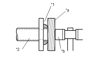
(a) Inspect the free length.
|
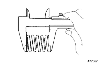
(1) Using a vernier caliper, measure the free length of the compression spring. Free Length of Compression Spring:
If the length is not as specified, replace the compression spring. |
|
|
(b) Using a plastic hammer and a wooden block, tap in a new gasket until its surface is flush with the front exhaust pipe assembly. Text in Illustration
NOTICE:
|
|
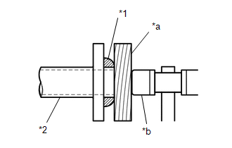
(c) Install 2 new gaskets to the front exhaust pipe assembly.
(d) Install the front exhaust pipe assembly to the exhaust manifold sub-assembly LH (TWC: front catalyst) and exhaust manifold sub-assembly RH (TWC: front catalyst) with 4 new nuts.
Torque:
62 N·m {632 kgf·cm, 46 ft·lbf}
|
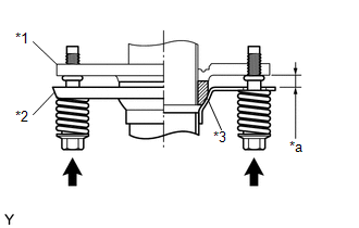
(e) Connect the front exhaust pipe assembly to the center exhaust pipe sub-assembly (TWC: rear catalyst) with the 2 compression springs and 2 bolts. Text in Illustration
Torque: 43 N·m {438 kgf·cm, 32 ft·lbf} NOTICE: After the installation, check that the gaps between the flanges of the front exhaust pipe assembly and center exhaust pipe assembly are consistent front-to-rear and left-to-right. |
|
(f) Connect the exhaust pipe clamp to the No. 1 exhaust pipe support bracket and tighten the bolt.
Torque:
21 N·m {214 kgf·cm, 15 ft·lbf}
(g) Engage the 6 clamps to connect the oxygen sensor (for bank 2 sensor 2) wire to the 2 wire harness clamp brackets.
(h) Connect the oxygen sensor (for bank 2 sensor 2) connector.
(i) Pass the connector through the hole to the inside of the vehicle and install the grommet of the oxygen sensor (for bank 1 sensor 2) wire.
(j) Connect the oxygen sensor (for bank 1 sensor 2) connector.
12. INSTALL FRONT EXHAUST PIPE ASSEMBLY (for AWD)
(a) Install a new gasket to the front exhaust pipe assembly.
(b) Install the front exhaust pipe assembly to the exhaust manifold sub-assembly LH (TWC: front catalyst) with the 2 nuts.
Torque:
62 N·m {632 kgf·cm, 46 ft·lbf}
(c) Inspect the free length.
|
(1) Using a vernier caliper, measure the free length of the compression spring. Free Length of Compression Spring:
If the length is not as specified, replace the compression spring. |
|
|
(d) Using a plastic hammer and a wooden block, tap in a new gasket until its surface is flush with the front No. 3 exhaust pipe sub-assembly. Text in Illustration
NOTICE:
|
|
(e) Install 2 new gaskets to the front No. 3 exhaust pipe sub-assembly.
(f) Install the front No. 3 exhaust pipe sub-assembly to the exhaust manifold sub-assembly RH (TWC: front catalyst) and front exhaust pipe assembly with 2 new nuts and 2 new bolts.
Torque:
Bolt :
43 N·m {438 kgf·cm, 32 ft·lbf}
Nut :
62 N·m {632 kgf·cm, 46 ft·lbf}
|
(g) Connect the front No. 3 exhaust pipe sub-assembly to the center exhaust pipe sub-assembly (TWC: rear catalyst) with the 2 compression springs and 2 bolts. Text in Illustration
Torque: 43 N·m {438 kgf·cm, 32 ft·lbf} NOTICE: After the installation, check that the gaps between the flanges of the front No. 3 exhaust pipe sub-assembly and center exhaust pipe assembly are consistent front-to-rear and left-to-right. |
|
(h) Connect the exhaust pipe clamp to No. 1 exhaust pipe support bracket and tighten the bolt.
Torque:
21 N·m {214 kgf·cm, 15 ft·lbf}
(i) Engage the 6 clamps to connect the oxygen sensor (for bank 2 sensor 2) wire to the 2 wire harness clamp brackets.
(j) Connect the oxygen sensor (for bank 2 sensor 2) connector.
(k) Pass the connector through the hole to the inside of the vehicle and install the grommet of the oxygen sensor (for bank 1 sensor 2) wire.
(l) Connect the oxygen sensor (for bank 1 sensor 2) connector.
13. INSTALL PROPELLER WITH CENTER BEARING SHAFT ASSEMBLY (for AWD)
(See page
)
14. INSTALL NO. 2 ENGINE UNDER COVER (for AWD)
(a) Install the No. 2 engine under cover with the 2 bolts, 2 screws and clip.
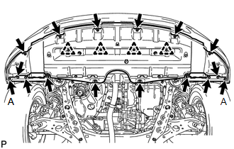
15. INSTALL NO. 1 ENGINE UNDER COVER
|
(a) Install the No. 1 engine under cover with the 2 bolts, 6 screws and 4 clips. |
|
(b) Install the front wheel opening extension pad RH and front wheel opening extension pad LH with the 8 screws.
Torque:
Screw A :
7.0 N·m {71 kgf·cm, 62 in·lbf}
16. INSTALL INSTRUMENT PANEL FINISH PANEL END LH
17. INSTALL V-BANK COVER SUB-ASSEMBLY
18. INSTALL RADIATOR ASSEMBLY
(See page
)
19. INSPECT FOR EXHAUST GAS LEAK
|
|
|