| Last Modified: 08-28-2024 | 6.11:8.1.0 | Doc ID: RM100000000VIDU |
| Model Year Start: 2016 | Model: Sienna | Prod Date Range: [12/2015 - 08/2016] |
| Title: 2GR-FE FUEL: FUEL TANK: INSTALLATION; 2016 MY Sienna [12/2015 - 08/2016] | ||
INSTALLATION
PROCEDURE
1. INSTALL FUEL TANK BAND
(a) Install the 3 fuel tank bands with the 6 clips.
2. INSTALL FUEL TANK CUSHION
(a) Install the 6 fuel tank cushions.
3. INSTALL NO. 2 FUEL TANK CUSHION
(a) Install the 2 No. 2 fuel tank cushions.
4. INSTALL FUEL TANK SIDE PLATE
(a) Install the fuel tank side plate and fuel tank bracket sub-assembly with the nut and bolt.
Torque:
30 N·m {306 kgf·cm, 22 ft·lbf}
5. INSTALL FUEL TANK TO FILLER PIPE HOSE
(a) Install the fuel tank to filler pipe hose.
6. INSTALL NO. 1 FUEL SUCTION TUBE SET GASKET
(a) Ensure gasket groove is clean and free of foreign particles.
(b) Install a new gasket onto the fuel tank.
(c) Make sure that the gasket sits in the groove.
7. INSTALL FUEL TANK OVERFILL CHECK VALVE ASSEMBLY
|
(a) Align the protrusion of the fuel tank overfill check valve assembly with the cutout of the tank suction tube support and install the fuel tank overfill check valve assembly. Text in Illustration
|
|
|
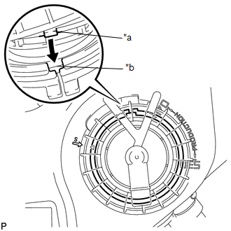
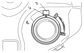
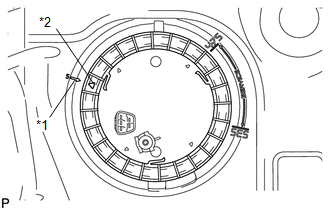
(b) Align marks on the fuel pump gauge retainer and the fuel tank. Text in Illustration
|
|
(c) Position the fuel pump gauge retainer on top of the fuel tank overfill check valve assembly flange while pushing down the flange on center.
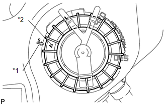
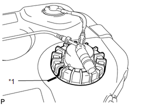
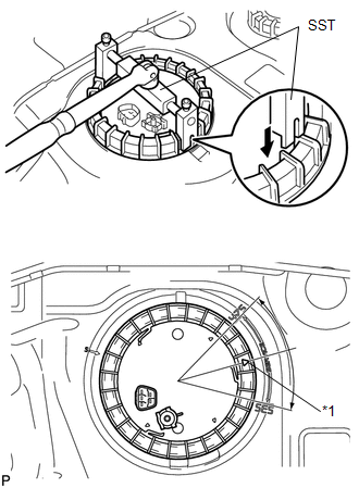
(d) While holding the fuel tank overfill check valve assembly, tighten the fuel pump gauge retainer one complete turn by hand*1.
NOTICE:
- Make sure the fuel tank overfill check valve assembly anti-rotation tab is in the groove during above operation.
- "S" arrow on the fuel tank indicates 0 degrees position.
|
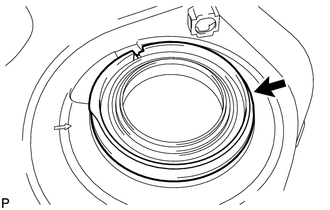
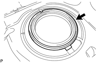
(e) Ensure that no cross threading occurred during installation by checking the gap between the fuel pump gauge retainer and the fuel tank. Confirm that the gap is even. If cross threading occurred, remove the fuel pump gauge retainer and repeat step*1. Text in Illustration
|
|
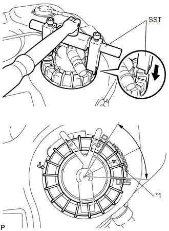
(f) Using SST, tighten the fuel pump gauge retainer.
SST: 09808-14020
09808-01410
09808-01420
09808-01430
NOTICE:
- No ratcheting effect allowed when tightening the fuel pump gauge retainer.
- No grease or lubrication allowed on parts during installation.
HINT:
- Align the ribs of the fuel pump gauge retainer with the tips of SST.
(g) Install the fuel pump gauge retainer by one and a half turns so that the start mark on the fuel pump gauge retainer is between 470° and 530° from the start position.
(h) If the start mark does not reach 470°, confirm that no cross threading occurred by measuring the gap between the fuel pump gauge retainer and the fuel tank.
If cross threading occurred, replace the fuel tank overfill check valve assembly, the gasket and the tank suction tube support.
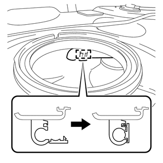
(i) Replace the tank suction tube support.
|
(1) Remove the tank suction tube support from the fuel tank. |
|
|
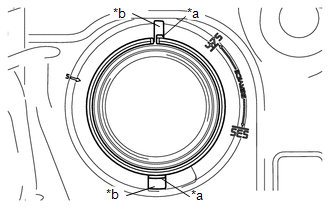
(2) Install the tank suction tube support to the fuel tank as shown in the illustration. Text in Illustration
|
|
|
(j) Engage the hose clamp. |
|
|
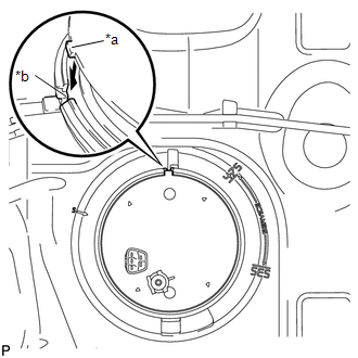
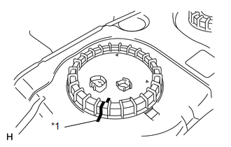
(k) Put a mark on the fuel pump gauge retainer and the fuel tank with paint. This will be the evidence that the fuel pump gauge retainer has been removed. Text in Illustration
|
|
(l) Line up the pipe and connector and push them together until a "click" sound is heard (See page
![2016 MY Sienna [12/2015 - 08/2016]; 2GR-FE FUEL: FUEL SYSTEM: PRECAUTION](/t3Portal/stylegraphics/info.gif) ).
).
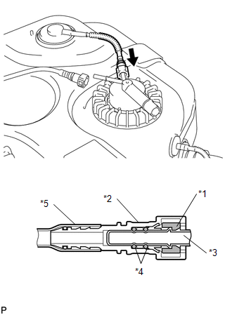
Text in Illustration
|
*1 |
Retainer |
|
*2 |
Fuel Tube Connector |
|
*3 |
Fuel Pipe |
|
*4 |
O-Ring |
|
*5 |
Nylon Tube |

|
Push |
NOTICE:
- Check that there are no scratches or foreign objects on the connecting part.
- Check that the tube is inserted securely.
- Check that the tube is securely connected by pulling on it.
(m) Line up the pipe and connector and push them together until a "click" sound is heard (See page
![2016 MY Sienna [12/2015 - 08/2016]; 2GR-FE FUEL: FUEL SYSTEM: PRECAUTION](/t3Portal/stylegraphics/info.gif) ).
).
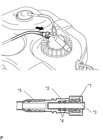
Text in Illustration
|
*1 |
Retainer |
|
*2 |
Fuel Tube Connector |
|
*3 |
Fuel Pipe |
|
*4 |
O-Ring |
|
*5 |
Nylon Tube |

|
Push |
NOTICE:
- Check that there are no scratches or foreign objects on the connecting part.
- Check that the tube is inserted securely.
- Check that the tube is securely connected by pulling on it.
8. INSTALL FUEL SUCTION TUBE SET GASKET
(a) Ensure gasket groove is clean and free of foreign particles.
(b) Install a new gasket onto the fuel tank.
(c) Make sure that the gasket sits in the groove.
9. INSTALL FUEL SUCTION WITH PUMP AND GAUGE TUBE ASSEMBLY
|
(a) Align the protrusion of the fuel suction with pump and gauge tube assembly with the cutout of the tank suction tube support and install the fuel suction with pump and gauge tube assembly. Text in Illustration
NOTICE: Do not bend the arm of the fuel sender gauge. |
|
10. INSTALL FUEL PUMP GAUGE RETAINER
|
(a) Align marks on the fuel pump gauge retainer and the fuel tank. Text in Illustration
|
|
(b) Position the fuel pump gauge retainer on top of the fuel suction with pump and gauge tube assembly flange while pushing down the flange on center.
(c) While holding the fuel suction with pump and gauge tube assembly, tighten the fuel pump gauge retainer one complete turn by hand*1.
NOTICE:
- Make sure the fuel suction with pump and gauge tube assembly anti-rotation tab is in the groove during above operation.
- "S" arrow on the fuel tank indicates 0 degrees position.
|
(d) Ensure that no cross threading occurred during installation by checking the gap between the fuel pump gauge retainer and the fuel tank. Confirm that the gap is even. If cross threading occurred, remove the fuel pump gauge retainer and repeat step*1. Text in Illustration
|
|
(e) Using SST, tighten the fuel pump gauge retainer to the specified torque.
SST: 09808-14020
09808-01410
09808-01420
09808-01430
Torque:
80 N·m {816 kgf·cm, 59 ft·lbf}
HINT:
Align the ribs of the fuel pump gauge retainer with the tips of SST.
NOTICE:
- No ratcheting effect allowed when tightening the fuel pump gauge retainer.
- No grease or lubrication allowed on parts during installation.
(f) Install the fuel pump gauge retainer by one and a half turns so that the start mark on the fuel pump gauge retainer is between 475° and 535° from the start position.
(g) If the start mark does not reach 475°, confirm that no cross threading occurred by measuring the gap between the fuel pump gauge retainer and the fuel tank.
If cross threading occurred, replace the fuel pump gauge retainer, the gasket and the tank suction tube support.
(h) Replace the tank suction tube support.
|
(1) Remove the tank suction tube support from the fuel tank. |
|
|
(2) Install the tank suction tube support to the fuel tank as shown in the illustration. Text in Illustration
|
|
|
(i) Put a mark on the fuel pump gauge retainer and the fuel tank with paint. This will be the evidence that the fuel pump gauge retainer has been removed. Text in Illustration
|
|
11. INSTALL FUEL TANK VENT HOSE
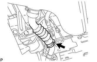
(a) Engage the 4 clamps and install the fuel tank vent hose and hose clamp.
|
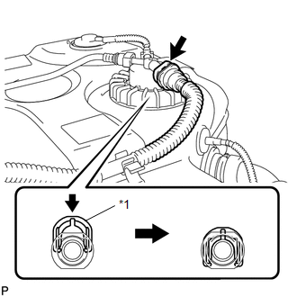
(b) Line up the pipe and connector and push them together until a "click" sound is heard. Text in Illustration
|
|
(c) Lock it by pushing in the retainer as shown in the illustration.
NOTICE:
- Check that there are no scratches or foreign objects on the connecting part.
- Check that the fuel tank vent hose is inserted securely.
- After installing the retainer, check that the fuel tank vent hose is securely connected by pulling on it.
HINT:
The quick connector cannot be locked when the tube is not inserted securely.
12. INSTALL CHARCOAL CANISTER OUTLET TUBE SUB-ASSEMBLY
(a) Engage the 4 clamps and install the charcoal canister outlet tube sub-assembly.
13. INSTALL FUEL TANK MAIN TUBE SUB-ASSEMBLY
(a) Engage the 4 guides and install the fuel tank main tube sub-assembly.
(b) Insert the fuel tank main tube into the fuel suction tube assembly plug and lock it with the tube joint clip.
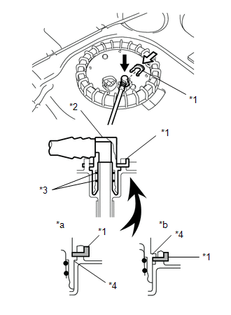
Text in Illustration
|
*1 |
Tube Joint Clip |
|
*2 |
Fuel Tube Connector |
|
*3 |
O-Ring |
|
*4 |
Collar |
|
*a |
OK |
|
*b |
NG |

|
Push Down |

|
Push |
NOTICE:
- Check that there are no scratches or foreign objects on the connecting part.
- Check that the fuel tank main tube is inserted securely.
- Check that the tube joint clip is on the collar of the main tube.
- After installing the tube joint clip, check that the fuel tank main tube assembly is securely connected by pulling on it.
14. INSTALL FUEL TANK ASSEMBLY
(a) Clean and degrease the bolt holes.
(b) Set the fuel tank and 3 fuel tank bands on the engine lifter.
(c) Slowly raise the engine lifter and install the fuel tank onto the vehicle.
NOTICE:
Make sure that the fuel tank does not fall.
(d) While operating the engine lifter, engage the 4 guides for the wire harness and connect the fuel pump connector, then install the fuel tank and the 3 fuel tank bands to the vehicle.
(e) Tighten the 6 set bolts of the 3 fuel tank bands.
Torque:
33 N·m {337 kgf·cm, 24 ft·lbf}
(f) Install the 2 wire harness clamps.
(g) Line up the pipe and connector and push them together until a "click" sound is heard (See page
![2016 MY Sienna [12/2015 - 08/2016]; 2GR-FE FUEL: FUEL SYSTEM: PRECAUTION](/t3Portal/stylegraphics/info.gif) ).
).
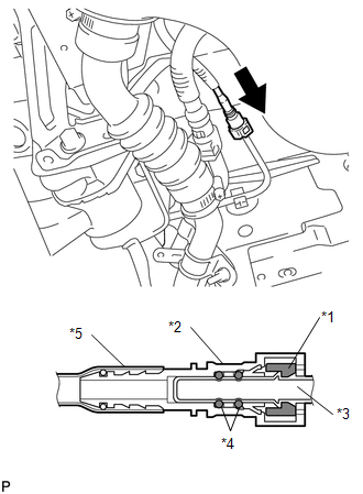
Text in Illustration
|
*1 |
Retainer |
|
*2 |
Fuel Tube Connector |
|
*3 |
Fuel Pipe |
|
*4 |
O-Ring |
|
*5 |
Nylon Tube |

|
Push |
NOTICE:
- Check if there is any damage or foreign objects on the connected part.
- After connecting, check if the connector and the pipe are securely connected by pulling on them.
(h) Connect the charcoal canister outlet tube (See page
![2016 MY Sienna [12/2015 - 08/2016]; 2GR-FE FUEL: FUEL SYSTEM: PRECAUTION](/t3Portal/stylegraphics/info.gif) ).
).
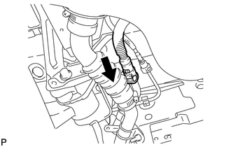
Text in Illustration

|
Push |
NOTICE:
- Check that there are no scratches or foreign objects on the connecting part.
- Check that the charcoal canister outlet tube sub-assembly is inserted securely.
- Check that the charcoal canister outlet tube sub-assembly is securely connected by pulling on it.
|
(i) Connect the fuel tank to filler pipe hose. |
|
15. CONNECT FUEL TANK MAIN TUBE SUB-ASSEMBLY
(a) Line up the pipe and connector and push them together until a "click" sound is heard (See page
![2016 MY Sienna [12/2015 - 08/2016]; 2GR-FE FUEL: FUEL SYSTEM: PRECAUTION](/t3Portal/stylegraphics/info.gif) ).
).
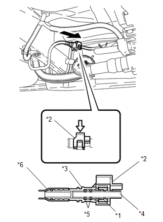
Text in Illustration
|
*1 |
Retainer |
|
*2 |
Fuel Tube Connector Cover |
|
*3 |
Fuel Tube Connector |
|
*4 |
Fuel Pipe |
|
*5 |
O-Ring |
|
*6 |
Nylon Tube |

|
Push |

|
Down |
(b) Push the fuel tube connector cover in to lock it.
NOTICE:
- Check that there are no scratches or foreign objects on the connecting part.
- Check that the fuel tank main tube is inserted securely.
- After installing the fuel tube connector cover, check that the fuel tank main tube is securely connected by pulling on it.
16. CONNECT CHARCOAL CANISTER OUTLET TUBE SUB-ASSEMBLY
17. CONNECT FUEL TANK VENT HOSE
18. INSTALL NO. 1 FUEL TANK HEAT INSULATOR (for 2WD)
(a) Install the No. 1 fuel tank heat insulator with the 4 nuts.
Torque:
6.0 N·m {61 kgf·cm, 53 in·lbf}
19. INSTALL CENTER EXHAUST PIPE ASSEMBLY (for 2WD)
|
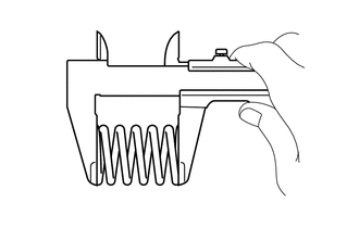
(a) Using a vernier caliper, measure the free length of the compression spring. Minimum Length: 38.86 mm (1.5299 in.) If the length is not as specified, replace the compression spring. |
|
|
(b) Using a plastic hammer and a wooden block, tap in a new exhaust pipe gasket until its surface is flush with the front exhaust pipe assembly. Text in Illustration
NOTICE:
|
|
(c) Install a new gasket to the center exhaust pipe assembly.
(d) Hang the center exhaust pipe assembly with the 2 exhaust pipe supports.
(e) Install the 2 compression springs and 4 bolts.
Torque:
43 N·m {438 kgf·cm, 32 ft·lbf}
20. INSTALL PROPELLER WITH CENTER BEARING SHAFT ASSEMBLY (for AWD)
21. ADD FUEL
22. INSPECT FOR FUEL LEAK
23. INSPECT FOR EXHAUST GAS LEAK
24. INSTALL FUEL TANK FILLER HOSE COVER
(a) Install the 3 bolts and the fuel tank filler hose cover.
Torque:
5.0 N·m {51 kgf·cm, 44 in·lbf}
25. INSTALL REAR FLOOR NO. 2 CROSSMEMBER BRACE LH
(a) Install the rear floor No. 2 crossmember brace LH with 2 bolts.
Torque:
28 N·m {286 kgf·cm, 21 ft·lbf}
26. INSTALL CHARCOAL CANISTER PROTECTOR
|
|
|
