| Last Modified: 08-28-2024 | 6.11:8.1.0 | Doc ID: RM100000000VIDM |
| Model Year Start: 2016 | Model: Sienna | Prod Date Range: [12/2015 - 08/2016] |
| Title: 2GR-FE FUEL: FUEL INJECTOR: INSTALLATION; 2016 MY Sienna [12/2015 - 08/2016] | ||
INSTALLATION
PROCEDURE
1. REMOVE INJECTOR VIBRATION INSULATOR
(a) Install 6 new injector vibration insulators to the intake manifold.
2. INSTALL FUEL INJECTOR ASSEMBLY
(a) Apply a light coat of spindle oil or gasoline to new O-rings, and install them to each injector.
(b) Apply a light coat of spindle oil or gasoline where the fuel delivery pipe contacts each O-ring.

Text in Illustration

|
Turn |

|
Push |
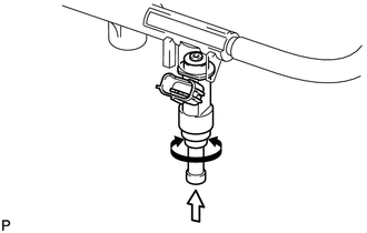
(c) Push and twist each fuel injector to install them into the fuel delivery pipe.
(d) Position each fuel injector connector outward.
NOTICE:
- Be careful not to twist the O-rings.
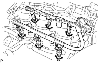
- After installing a fuel injector, check that it turns smoothly. If not, reinstall it with a new O-ring.
(e) Place the fuel delivery pipe with the 6 fuel injectors in position on the intake manifold.
NOTICE:
Be careful not to drop the fuel injectors when installing the fuel delivery pipe.
|
(f) Temporarily install the 5 bolts which are used to hold the fuel delivery pipe to the intake manifold. NOTICE: After installing the fuel injectors, check that they turn smoothly. If not, reinstall the injectors with new O-rings. |
|
(g) Tighten the 5 bolts which are used to hold the fuel delivery pipe to the intake manifold.
Torque:
21 N·m {214 kgf·cm, 15 ft·lbf}
(h) Connect the 3 fuel injector connectors.
3. CONNECT FUEL TUBE SUB-ASSEMBLY
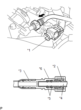
(a) Line up the pipe and connector and push them together until a "click" sound is heard (See page
![2016 MY Sienna [12/2015 - 08/2016]; 2GR-FE FUEL: FUEL SYSTEM: PRECAUTION](/t3Portal/stylegraphics/info.gif) ).
).

Text in Illustration
|
*1 |
Fuel Pipe Clamp |
|
*2 |
Retainer |
|
*3 |
Nylon Tube |
|
*4 |
Fuel Pipe |
|
*5 |
O-ring |
|
*6 |
Fuel Tube Connector |

|
Push |
NOTICE:
- Check that there are no scratches or foreign objects on the connecting part.
- Check that the tube is inserted securely.
- Check that the tube is securely connected by pulling on it.
(b) Install the fuel pipe clamp.
4. INSTALL FUEL HOSE PROTECTOR
(a) Install the fuel hose protector with the 2 bolts and nut.
Torque:
Bolt :
21 N·m {214 kgf·cm, 15 ft·lbf}
Nut :
10 N·m {102 kgf·cm, 7 ft·lbf}
(b) Connect the 2 harness clamps and 3 fuel injector connectors.
5. INSTALL NO. 2 ENGINE MOUNTING STAY RH
(a) Install the No. 2 engine mounting stay RH with the bolt.
Torque:
21 N·m {214 kgf·cm, 15 ft·lbf}
6. INSTALL NO. 2 ENGINE MOUNTING STAY RH
(a) Install the No. 2 engine mounting stay RH with the bolt and 2 nuts.
Torque:
Bolt :
38 N·m {387 kgf·cm, 28 ft·lbf}
Nut :
23 N·m {235 kgf·cm, 17 ft·lbf}
7. INSTALL INTAKE AIR SURGE TANK ASSEMBLY
8. INSPECT FOR FUEL LEAK
|
|
|
