| Last Modified: 08-28-2024 | 6.11:8.1.0 | Doc ID: RM100000000VID1 |
| Model Year Start: 2016 | Model: Sienna | Prod Date Range: [12/2015 - 08/2016] |
| Title: 2GR-FE ENGINE MECHANICAL: ENGINE UNIT: REASSEMBLY; 2016 MY Sienna [12/2015 - 08/2016] | ||
REASSEMBLY
PROCEDURE
1. INSTALL ENGINE REAR OIL SEAL
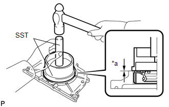
(a) Place the oil seal retainer on wooden blocks.
|
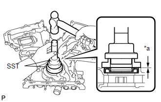
(b) Using SST, tap in a new engine rear oil seal until its surface is flush with the engine rear oil seal retainer edge. SST: 09223-15030 SST: 09950-70010 09951-07100 Text in Illustration
NOTICE:
|
|
2. INSTALL ENGINE REAR OIL SEAL RETAINER
|
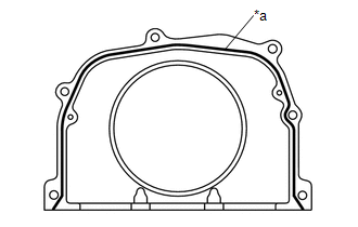
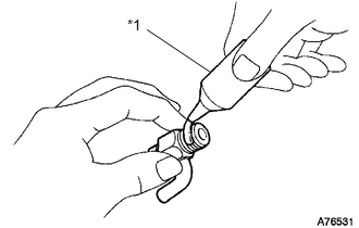
(a) Apply seal packing in a continuous line as shown in the illustration. Text in Illustration
Seal packing: Toyota Genuine Seal Packing Black, Three Bond 1207B or equivalent Seal diameter: 2.0 to 3.0 mm (0.0787 to 0.118 in.) NOTICE:
|
|
|
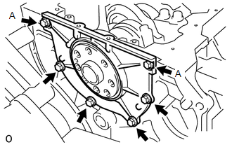
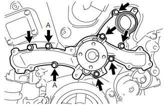
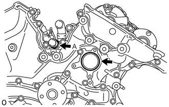
(b) Install the engine rear oil seal retainer with the 6 bolts. Torque: 10 N·m {102 kgf·cm, 7 ft·lbf} NOTICE: Be sure to apply adhesive 1324 to the bolts in the places indicated by A before installing them. Adhesive: Toyota Genuine Adhesive 1324, Three Bond 1324 or equivalent |
|
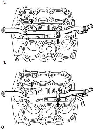
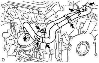
3. INSTALL WATER INLET PIPE
Text in Illustration
|
*a |
w/o Oil Cooler |
|
*b |
w/ Oil Cooler |
(a) Install the water inlet pipe with the 2 bolts.
Torque:
10 N·m {102 kgf·cm, 7 ft·lbf}
(b) Install the No. 1 water by-pass hose.
4. INSTALL CYLINDER HEAD GASKET RH
![2016 MY Sienna [12/2015 - 08/2016]; 2GR-FE ENGINE MECHANICAL: CYLINDER HEAD GASKET: INSTALLATION+](/t3Portal/stylegraphics/info.gif)
5. INSTALL CYLINDER HEAD SUB-ASSEMBLY RH
6. INSTALL CYLINDER HEAD GASKET LH
7. INSTALL CYLINDER HEAD SUB-ASSEMBLY LH
8. INSTALL VALVE STEM CAP
9. INSTALL VALVE LASH ADJUSTER ASSEMBLY
10. INSTALL NO. 1 VALVE ROCKER ARM SUB-ASSEMBLY
11. INSTALL NO. 3 CAMSHAFT
12. INSTALL NO. 4 CAMSHAFT
13. INSTALL CAMSHAFT BEARING CAP (for Bank 2)
14. INSTALL CAMSHAFT HOUSING SUB-ASSEMBLY LH
15. INSTALL CAMSHAFT
16. INSTALL NO. 2 CAMSHAFT
17. INSTALL CAMSHAFT BEARING CAP (for Bank 1)
18. INSTALL CAMSHAFT HOUSING SUB-ASSEMBLY RH
19. INSTALL NO. 3 CHAIN TENSIONER ASSEMBLY
20. INSTALL CAMSHAFT TIMING GEARS AND NO. 2 CHAIN (for Bank 2)
21. INSTALL NO. 2 CHAIN TENSIONER ASSEMBLY
22. INSTALL CAMSHAFT TIMING GEARS AND NO. 2 CHAIN (for Bank 1)
23. INSTALL NO. 1 CHAIN VIBRATION DAMPER
|
(a) Install the No. 1 chain vibration damper with the 2 bolts. Torque: 23 N·m {230 kgf·cm, 17 ft·lbf} |
|
24. INSTALL NO. 2 CHAIN VIBRATION DAMPER
(a) Install the 2 No. 2 chain vibration dampers.
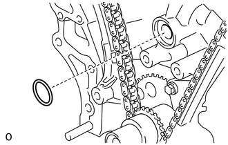
25. INSTALL CRANKSHAFT TIMING SPROCKET
|
(a) Install the 2 keys and crankshaft timing sprocket as shown in the illustration. |
|
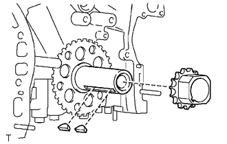
26. INSTALL IDLE SPROCKET ASSEMBLY
|
(a) Apply a light coat of engine oil to the rotating surface of the No. 1 idle gear shaft. Text in Illustration
|
|
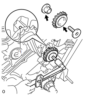
(b) Temporarily install the No. 1 idle gear shaft and idle sprocket with the No. 2 idle gear shaft while aligning the knock pin of the No. 1 idle gear shaft with the knock pin groove of the cylinder block.
NOTICE:
Be careful of the idle gear installation position.
HINT:
Check that no foreign objects are on the No. 1 and No. 2 idle gear shafts.
(c) Using a 10 mm hexagon wrench, tighten the No. 2 idle gear shaft.
Torque:
60 N·m {612 kgf·cm, 44 ft·lbf}
HINT:
After installing the idle sprocket assembly, check that the idle sprocket turns smoothly.
27. INSTALL CHAIN SUB-ASSEMBLY
|
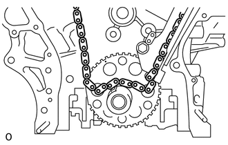
(a) Align the mark plates and timing marks as shown in the illustration and install the chain. Text in Illustration
HINT: The camshaft mark plates are orange. |
|
|
(b) Do not pass the chain over the crankshaft, just temporarily place it on the crankshaft. |
|
|
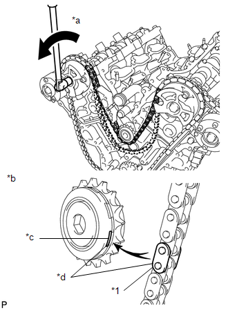
(c) Turn the camshaft timing gear assembly on bank 1 counterclockwise to tighten the chain between the banks. Text in Illustration
NOTICE: When the idle sprocket assembly is reused, align the chain plate with the mark where the plate had been in order to tighten the chain between the banks. |
|
|
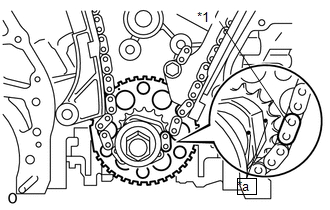
(d) Align the mark plate and timing marks as shown in the illustration and install the chain onto the crankshaft timing sprocket. Text in Illustration
HINT: The crankshaft mark plate is yellow. |
|
(e) Temporarily tighten the pulley set bolt.
|
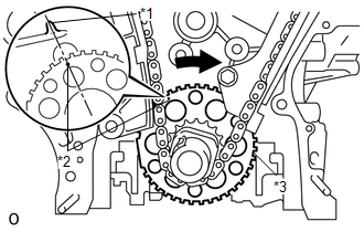
(f) Turn the crankshaft clockwise to set it to the RH block bore center line (TDC/compression). Text in Illustration
|
|
28. INSTALL CHAIN TENSIONER SLIPPER
(a) Install the chain tensioner slipper.
29. INSTALL NO. 1 CHAIN TENSIONER ASSEMBLY
|
(a) Move the stopper plate upward to release the lock, and push the plunger deep into the tensioner. Text in Illustration
|
|
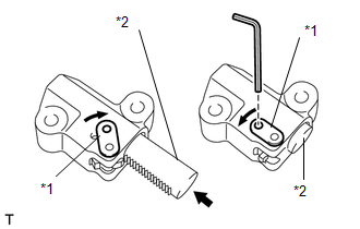
(b) Move the stopper plate downward to set the lock, and insert a hexagon wrench into the hole of the stopper plate.
|
(c) Install the No. 1 chain tensioner assembly with the 2 bolts. Torque: 10 N·m {102 kgf·cm, 7 ft·lbf} |
|
(d) Remove the hexagon wrench from the No. 1 chain tensioner assembly.
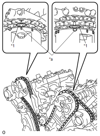
30. INSPECT VALVE TIMING
(a) Check the camshaft timing marks.
NOTICE:
- Check each timing mark from a viewpoint directly inline with the center of the camshaft and the timing mark on each camshaft timing gear.
- If the timing marks are checked from any other viewpoint, the valve timing may appear misaligned.
(b) Check that each camshaft timing mark is positioned as shown in the illustration.
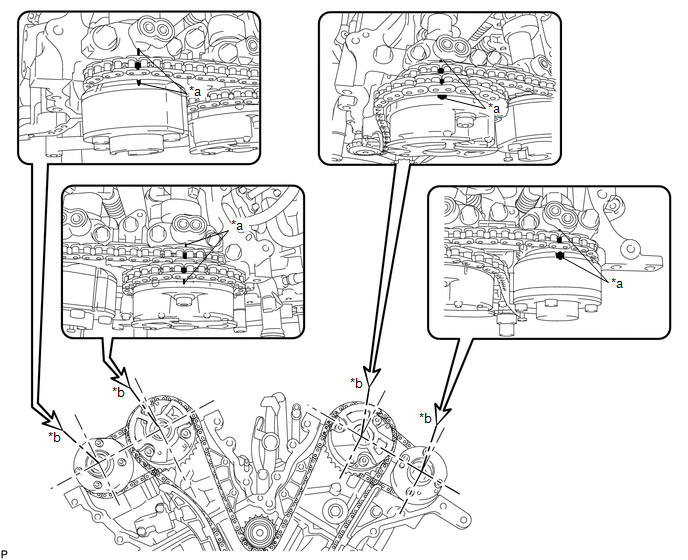
Text in Illustration
|
*a |
Timing Mark |
*b |
Viewpoint |
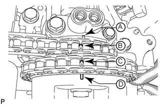
HINT:
For the intake camshaft:
Be sure to check mark A at the point when marks B, C, and D are positioned in line. If the marks are checked from any other viewpoint, they cannot be checked correctly.
(c) If the valve timing is misaligned, reinstall the timing chain.
(d) Remove the pulley set bolt.
31. INSTALL TIMING CHAIN CASE OIL SEAL
|
(a) Using SST, tap in a new timing chain case oil seal until its surface is flush with the timing gear case edge. Text in Illustration
SST: 09223-22010 SST: 09506-35010 Oil seal tap in depth: 0 to 1.0 mm (0 to 0.0394 in.) NOTICE:
|
|
32. INSTALL WATER PUMP ASSEMBLY
|
(a) Install a new water pump gasket and the water pump assembly with the 8 bolts. Torque: 11 N·m {112 kgf·cm, 8 ft·lbf} NOTICE: Be sure to replace the bolts indicated by A with new ones or reuse them after applying adhesive 1344. |
|
33. INSTALL TIMING CHAIN COVER SUB-ASSEMBLY
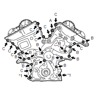
(a) Apply seal packing in a continuous line to the engine unit as shown in the following illustration.
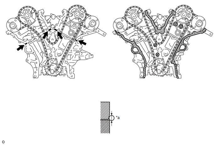
Text in Illustration
|
*a |
Seal Diameter: 3.0 mm or more |

|
Seal Packing |

|
Be sure to clean and grease the contact surface |
- |
- |
Seal packing:
Toyota Genuine Seal Packing Black, Three Bond 1207B or equivalent
Seal diameter:
3.0 mm (0.118 in.)
NOTICE:
- Be sure to clean and degrease the contact surfaces, especially the surfaces indicated by C in the illustration.
- If there is oil on the contact surfaces, wipe them with an oil-free cloth before applying seal packing.
- Install the chain cover within 3 minutes.
- Do not start the engine for at least 2 hours after installing.
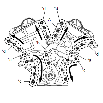
(b) Apply seal packing in a continuous line to the timing chain cover as shown in the following illustration.
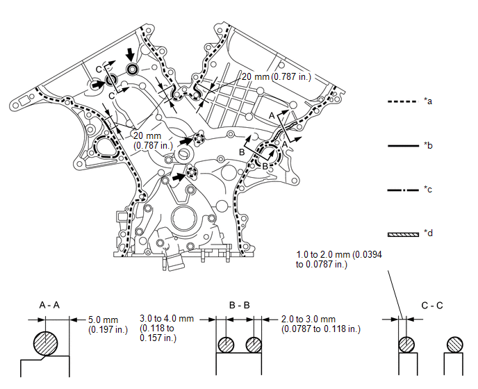
Text in Illustration
|
*a |
Dashed line area (Seal packing: Toyota Genuine Seal Packing Black, Three Bond 1207B or equivalent) |
*b |
Continuous line area (Seal packing: Toyota Genuine Seal Packing Black, Three Bond 1207B or equivalent) |
|
*c |
Alternate long and short dashed line area (Seal packing: Toyota Genuine Seal Packing 1282B, Three Bond 1282B or equivalent) |
*d |
Diagonal line area (Seal packing: Toyota Genuine Seal Packing Black, Three Bond 1207B or equivalent) |
|
|
Be sure to apply seal packing |
- |
- |
Seal packing:
Toyota Genuine Seal Packing Black, Three Bond 1207B or equivalent
Toyota Genuine Seal Packing 1282B, Three Bond 1282B or equivalent
NOTICE:
- If there is oil on the contact surfaces, wipe them with an oil-free cloth before applying seal packing.
- Install the chain cover within 3 minutes and tighten the bolts within 15 minutes after applying seal packing.
- Do not start the engine for at least 2 hours after installing.
Seal Packing Application Chart
|
Area |
Seal Packing Diameter |
Application Position from Inside Seal Line |
|---|---|---|
|
Continuous Line Area |
4.5 mm or more (0.177 in.) |
1.0 to 2.0 mm (0.0394 to 0.0787 in.) |
|
Alternate Long and Short Dashed Line Area |
3.5 mm or more (0.138 in.) |
2.0 to 3.0 mm (0.0787 to 0.118 in.) |
|
Dashed Line Area |
3.5 mm or more (0.138 in.) |
3.0 to 4.0 mm (0.118 to 0.158 in.) |
|
Diagonal Line Area |
6.0 mm or more (0.236 in.) |
5.0 mm (0.197 in.) |
|
(c) Install a new gasket. |
|
|
(d) Align the oil pump's drive rotor spline and the crankshaft as shown in the illustration. Install the spline and chain cover to the crankshaft. Text in Illustration
|
|
|
(e) Temporarily tighten the timing chain cover with the 23 bolts and 2 nuts. Text in Illustration
Bolt Length
NOTICE: Make sure that there is no oil on the bolt and nut threads. |
|
|
(f) Fully tighten the bolts in this order: Area 1 and Area 2. Text in Illustration
Torque: 21 N·m {214 kgf·cm, 15 ft·lbf} |
|
(g) Fully tighten the bolts in Area 3.
Torque:
21 N·m {214 kgf·cm, 15 ft·lbf}
HINT:
First tighten the upper bolts and nuts followed by lower bolts and nuts as shown in the illustration.
(h) Fully tighten the bolts in Area 4.
Torque:
Bolt A :
43 N·m {438 kgf·cm, 32 ft·lbf}
Torque:
Except bolt A :
21 N·m {214 kgf·cm, 15 ft·lbf}
HINT:
Tighten the bolts in the order of lower to upper as shown in the illustration.
(i) Install a new chain cover plate gasket and the chain cover plate with the 4 bolts.
Torque:
9.1 N·m {93 kgf·cm, 81 in·lbf}
34. INSTALL WATER INLET HOUSING
|
(a) Install 2 new O-rings. HINT: Apply a small amount of water or soapy water to O-ring (A) shown in the illustration before installation. |
|
|
(b) Install the 2 stud bolts. Torque: 4.0 N·m {41 kgf·cm, 35 in·lbf} |
|
|
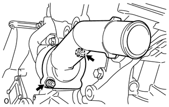
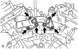
(c) Install the water inlet housing with the 2 bolts and nut. Text in Illustration
Torque: 10 N·m {102 kgf·cm, 7 ft·lbf} NOTICE: Be careful that the O-ring does not get caught between the parts. |
|
(d) Connect the No. 1 water by-pass hose.
(e) Apply adhesive around the drain cock.
Adhesive:
Toyota Genuine Adhesive 1324, Three Bond 1324 or equivalent
(f) Install the drain cock assembly to the water inlet housing.
Torque:
30 N·m {306 kgf·cm, 22 ft·lbf}
(g) Install the drain cock plug to the drain cock assembly.
Torque:
13 N·m {130 kgf·cm, 9 ft·lbf}
(h) Install a new gasket to the thermostat.
|
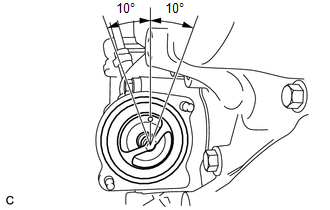
(i) Align the thermostat jiggle valve with the upper stud bolt, and insert the thermostat in the water inlet housing. HINT: The jiggle valve may be set within 10° of either side of the prescribed position. |
|
|
(j) Install the water inlet with the 2 nuts. Torque: 10 N·m {102 kgf·cm, 7 ft·lbf} |
|
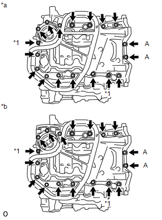
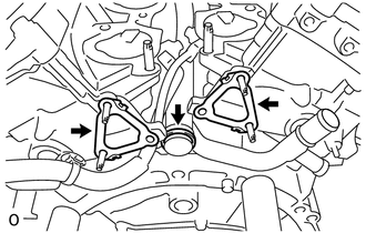
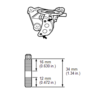
35. INSTALL NO. 1 FRONT ENGINE MOUNTING BRACKET LH
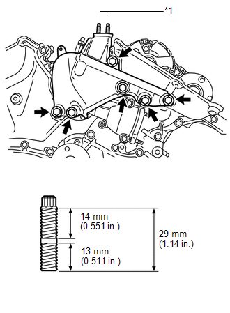
Text in Illustration
|
*1 |
Stud Bolt |
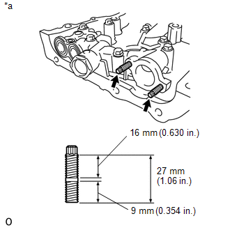
(a) Using an E8 "TORX" socket wrench, install the 2 stud bolts.
Torque:
10 N·m {102 kgf·cm, 7 ft·lbf}
(b) Install the No. 1 front engine mounting bracket LH with the 6 bolts.
Torque:
54 N·m {550 kgf·cm, 40 ft·lbf}
NOTICE:
- Install the water inlet and mounting bracket within 15 minutes after installing the chain cover.
- Do not start the engine for at least 2 hours after installation.
36. INSTALL NO. 1 OIL PAN BAFFLE PLATE
|
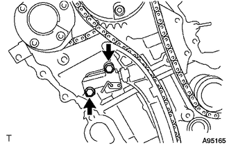
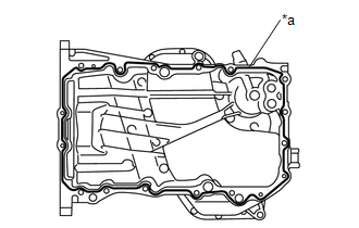
(a) Install the No. 1 oil pan baffle plate with the 7 bolts. Torque: 10 N·m {102 kgf·cm, 7 ft·lbf} HINT: Temporarily tighten the 7 bolts. Fully tighten the 2 bolts (A) shown in the illustration before tightening the other bolts. |
|
37. INSTALL OIL PAN SUB-ASSEMBLY
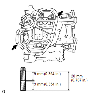
(a) Using an E8 "TORX" socket wrench, install the 4 stud bolts.
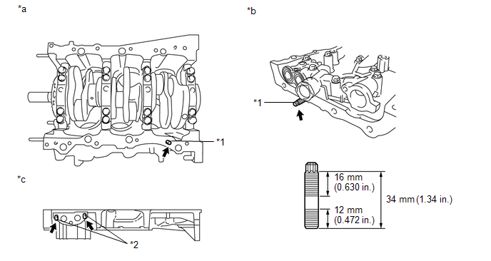
Text in Illustration
|
*1 |
Bolt A |
*2 |
Bolt B |
|
*a |
Lower Cylinder Block |
*b |
Timing Chain Cover |
|
*c |
Oil Pan LH Side (w/ Oil Cooler) |
- |
- |
Torque:
Bolt A :
10 N·m {102 kgf·cm, 7 ft·lbf}
Bolt B :
9.0 N·m {92 kgf·cm, 80 in·lbf}
|
(b) Install 2 new O-rings. |
|
|
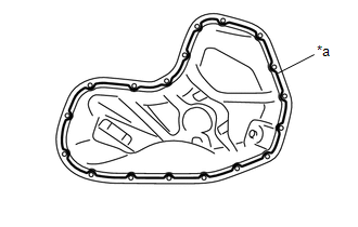
(c) Apply seal packing in a continuous line as shown in the illustration. Text in Illustration
Seal packing: Toyota Genuine Seal Packing Black, Three Bond 1207B or equivalent Seal diameter: 3.0 to 4.0 mm (0.118 to 0.157 in.) NOTICE:
|
|
|
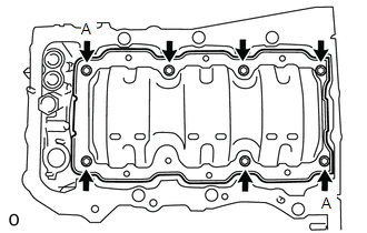
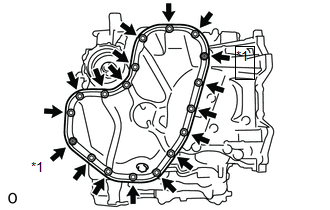
(d) Install the oil pan with the 16 bolts and 2 nuts. Text in Illustration
Torque: Bolts A : 10 N·m {102 kgf·cm, 7 ft·lbf} Except bolts A : 21 N·m {214 kgf·cm, 15 ft·lbf} |
|
38. INSTALL OIL STRAINER SUB-ASSEMBLY
|
(a) Using an E6 "TORX" socket, install the 2 stud bolts as shown in the illustration. Text in Illustration
Torque: 4.0 N·m {41 kgf·cm, 35 in·lbf} |
|
|
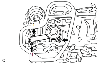
(b) Install a new gasket and the oil strainer sub-assembly with the bolt and 2 nuts. Text in Illustration
Torque: 10 N·m {102 kgf·cm, 7 ft·lbf} |
|
39. INSTALL NO. 2 OIL PAN SUB-ASSEMBLY
|
(a) Using an E6 "TORX" socket, install the 2 stud bolts as shown in the illustration. Torque: 4.0 N·m {41 kgf·cm, 35 in·lbf} |
|
|
(b) Apply seal packing in a continuous line as shown in the illustration. Text in Illustration
Seal packing: Toyota Genuine Seal Packing Black, Three Bond 1207B or equivalent Seal diameter: 3.0 to 4.0 mm (0.118 to 0.157 in.) NOTICE:
|
|
|
(c) Install the No. 2 oil pan sub-assembly with the 16 bolts and 2 nuts. Text in Illustration
Torque: 10 N·m {102 kgf·cm, 7 ft·lbf} |
|
40. INSTALL OIL PAN DRAIN PLUG
|
(a) Install a new oil pan drain plug gasket and the oil pan drain plug. Torque: 40 N·m {408 kgf·cm, 30 ft·lbf} |
|
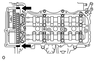
41. INSTALL CYLINDER HEAD COVER SUB-ASSEMBLY
(a) Apply seal packing as shown in the illustration.
Text in Illustration
|
|
Seal Packing |
Seal packing:
Toyota Genuine Seal Packing Black, Three Bond 1207B or equivalent
NOTICE:
- Remove any oil from the contact surface.
- Install the head cover within 3 minutes after applying seal packing.
- Do not start the engine for at least 2 hours after installing.
|
(b) Install 3 new gaskets as shown in the illustration. |
|
(c) Install a new cylinder head cover gasket to the cylinder head cover sub-assembly.
|
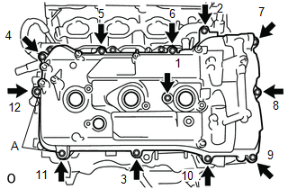
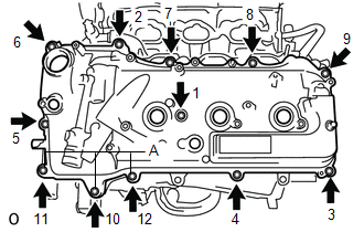
(d) Install the head cover with the 12 bolts and a new seal washer. Torque: Bolts A : 21 N·m {214 kgf·cm, 15 ft·lbf} Except bolts A : 10 N·m {102 kgf·cm, 7 ft·lbf} HINT: After tightening all bolts, check the tightening torque of 1 and 11. Retighten the bolt if necessary. |
|
42. INSTALL CYLINDER HEAD COVER SUB-ASSEMBLY LH
(a) Apply seal packing as shown in the illustration.
Text in Illustration
|
|
Seal Packing |
Seal packing:
Toyota Genuine Seal Packing Black, Three Bond 1207B or equivalent
NOTICE:
- Remove any oil from the contact surfaces.
- Install the cylinder head cover sub-assembly LH within 3 minutes after applying seal packing.
- Do not start the engine for at least 2 hours after installing.
|
(b) Install 3 new gaskets as shown in the illustration. |
|
(c) Install a new cylinder head cover gasket to the cylinder head cover sub-assembly LH.
|
(d) Install the cylinder head cover sub-assembly LH with the 12 bolts and a new seal washer. Torque: Bolts A : 21 N·m {214 kgf·cm, 15 ft·lbf} Except bolts A : 10 N·m {102 kgf·cm, 7 ft·lbf} HINT: After tightening all bolts, check the tightening torque of 1 and 10. Retighten the bolt if necessary. |
|
43. INSTALL WATER OUTLET
|
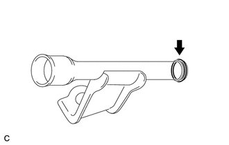
(a) Install 2 new gaskets and a new O-ring. HINT: Apply soapy water to the O-ring. |
|
|
(b) Install the water outlet with the 2 bolts and 4 nuts. Text in Illustration
Torque: 10 N·m {102 kgf·cm, 7 ft·lbf} NOTICE: Be careful that the O-ring does not get caught between the parts. |
|
44. INSTALL ENGINE OIL DIPSTICK GUIDE (w/ Oil Cooler)
|
(a) Apply a light coat of engine oil to a new O-ring and install it to the engine oil dipstick guide. |
|
|
(b) Install the engine oil dipstick guide. |
|
45. INSTALL ENGINE OIL DIPSTICK GUIDE (w/o Oil Cooler)
|
(a) Apply a light coat of engine oil to a new O-ring and install it to the engine oil dipstick guide. |
|
|
(b) Install the engine oil dipstick guide with the bolt. Torque: 21 N·m {214 kgf·cm, 15 ft·lbf} |
|
46. INSTALL NO. 1 OIL COOLER BRACKET (w/ Oil Cooler)
|
(a) Using an E8 "TORX" socket, install the 2 stud bolts as shown in the illustration. Torque: 10 N·m {102 kgf·cm, 7 ft·lbf} |
|
|
(b) Install a new gasket to the No. 1 oil cooler bracket. Text in Illustration
|
|
(c) Install the oil cooler pipe with the bolt and 2 nuts.
Torque:
21 N·m {214 kgf·cm, 15 ft·lbf}
|
(d) Install a new gasket to the No. 1 oil pan. |
|
(e) Install the No. 1 oil cooler bracket with oil cooler pipe with the 3 bolts and 3 nuts.
Torque:
21 N·m {214 kgf·cm, 15 ft·lbf}
47. INSTALL OIL COOLER ASSEMBLY (w/ Oil Cooler)
|
(a) Install a new O-ring. |
|
(b) Install the oil cooler assembly with the union bolt.
Torque:
68 N·m {693 kgf·cm, 50 ft·lbf}
|
(c) Install the 2 water by-pass hoses with the bolt, 2 clamps, and 4 clips. Torque: 10 N·m {102 kgf·cm, 7 ft·lbf} |
|
48. INSTALL CRANKSHAFT PULLEY
49. INSTALL OIL FILTER ELEMENT
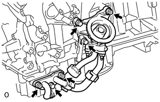
50. INSTALL CYLINDER BLOCK WATER DRAIN COCK SUB-ASSEMBLY
|
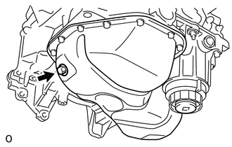
(a) Apply adhesive around the drain cock sub-assembly. Text in Illustration
Adhesive: Toyota Genuine Adhesive 1324, Three Bond 1324 or equivalent |
|
|
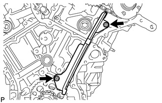
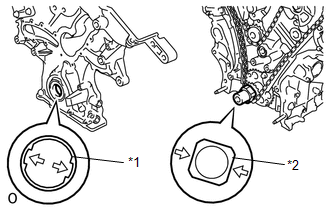
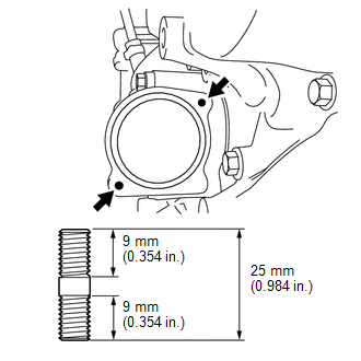
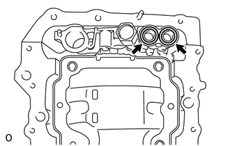
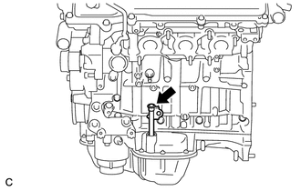
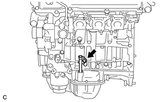
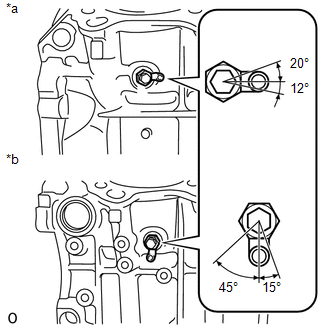
(b) Install the water drain cocks as shown in the illustration. Text in Illustration
Torque: 25 N·m {255 kgf·cm, 18 ft·lbf} NOTICE: Do not rotate the drain cocks more than 1 revolution (360°) after tightening the drain cocks with the specified torque. |
|
(c) Install the water drain cock plugs to the water drain cocks.
Torque:
13 N·m {130 kgf·cm, 9 ft·lbf}
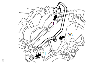
51. INSTALL NO. 1 OIL PIPE
(a) Make sure that there is no foreign matter on the mesh of the oil control valve filter LH.
NOTICE:
Do not touch the mesh when installing the oil control valve filter.
|
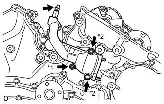
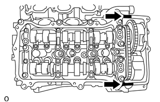
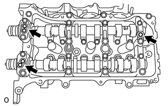
(b) Install the oil control valve filter LH to the oil pipe union. Install new gaskets and temporarily install the oil pipe (on the head cover side) with the union. Text in Illustration
|
|
(c) Install a new gasket and temporarily install the oil pipe (on the cylinder head side) with the union.
(d) Tighten the oil pipe union (on the head cover side).
Torque:
65 N·m {663 kgf·cm, 48 ft·lbf}
(e) Tighten the oil pipe union (on the cylinder head side).
Torque:
65 N·m {663 kgf·cm, 48 ft·lbf}
NOTICE:
If the link that connects the gaskets is broken, remove the connecting link by using side cutters or a similar tool.
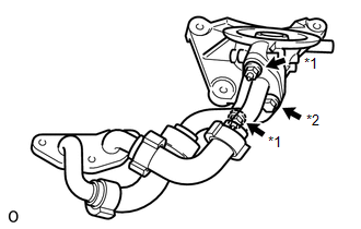
52. INSTALL OIL PIPE
(a) Make sure that there is no foreign matter on the mesh of the oil control valve filter RH.
NOTICE:
Do not touch the mesh when installing the oil control valve filter.
|
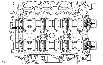
(b) Install the oil control valve filter RH to the oil pipe union. Install new gaskets and temporarily install the oil pipe (on the head cover side) with the union. Text in Illustration
|
|
(c) Install a new gasket and temporarily install the oil pipe (on the cylinder head side) with the union.
(d) Install the bolt (A) to the cylinder head.
Torque:
10 N·m {102 kgf·cm, 7 ft·lbf}
(e) Tighten the oil pipe union (on the head cover side).
Torque:
65 N·m {663 kgf·cm, 48 ft·lbf}
(f) Tighten the oil pipe union (on the cylinder head side).
Torque:
65 N·m {663 kgf·cm, 48 ft·lbf}
NOTICE:
If the link that connects the gaskets is broken, remove the connecting link by using side cutters or a similar tool.
53. INSTALL CRANKSHAFT POSITION SENSOR
54. INSTALL CAMSHAFT TIMING OIL CONTROL VALVE ASSEMBLY
(See page
)
55. INSTALL VVT SENSOR
(See page
)
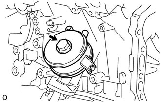
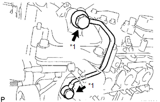
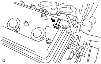
56. INSTALL VENTILATION VALVE SUB-ASSEMBLY
(a) Apply adhesive around the ventilation valve sub-assembly.
Adhesive:
Toyota Genuine Adhesive 1324, Three Bond 1324 or equivalent
|
(b) Using a deep socket wrench 19 mm, install the ventilation valve sub-assembly. Torque: 27 N·m {275 kgf·cm, 20 ft·lbf} |
|
57. INSTALL SPARK PLUG
58. INSTALL OIL FILLER CAP SUB-ASSEMBLY
(a) Install a new oil filler gasket.
(b) Install the oil filler cap sub-assembly.
|
|
|