| Last Modified: 08-28-2024 | 6.11:8.1.0 | Doc ID: RM100000000VICX |
| Model Year Start: 2016 | Model: Sienna | Prod Date Range: [12/2015 - 08/2016] |
| Title: 2GR-FE ENGINE MECHANICAL: ENGINE UNIT: INSPECTION; 2016 MY Sienna [12/2015 - 08/2016] | ||
INSPECTION
PROCEDURE
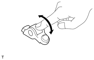
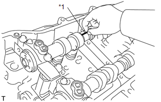
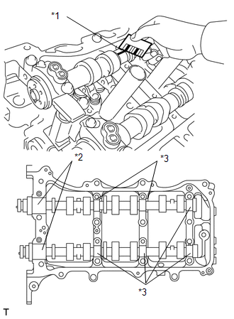
1. INSPECT NO. 1 VALVE ROCKER ARM SUB-ASSEMBLY
|
(a) Turn the roller by hand to check that it turns smoothly. HINT: If the roller does not turn smoothly, replace the No. 1 valve rocker arm sub-assembly. |
|
2. INSPECT VALVE LASH ADJUSTER ASSEMBLY
NOTICE:
- Keep the valve lash adjuster assembly free of dirt and foreign objects.
- Only use clean engine oil.
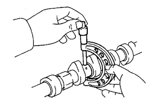
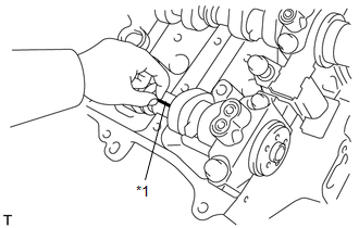
(a) Place the valve lash adjuster assembly into a container filled with engine oil.
|
(b) Insert the tip of SST into the valve lash adjuster assembly plunger and use the tip to press down on the check ball inside the plunger. Text in Illustration
SST: 09276-75010 |
|
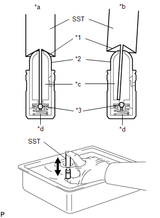
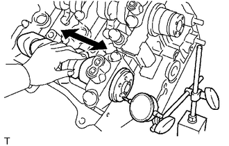
(c) Squeeze SST and valve lash adjuster assembly together to move the plunger up and down 5 to 6 times.
(d) Check the movement of the plunger and bleed the air.
OK:
Plunger moves up and down.
NOTICE:
When bleeding air from the high-pressure chamber, make sure that the tip of SST is actually pressing the check ball as shown in the illustration. If the check ball is not pressed, air will not bleed.
(e) After bleeding the air, remove SST. Then try to quickly and firmly press the plunger by hand.
OK:
Plunger is very difficult to move.
If the result is not as specified, replace the valve lash adjuster assembly.
3. INSPECT CAMSHAFT
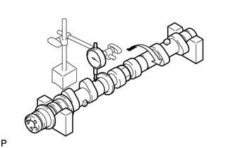
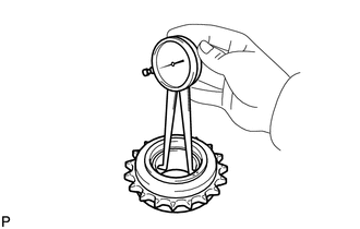
(a) Inspect the camshaft for runout.
(1) Place the camshaft on V-blocks.
|
(2) Using a dial indicator, measure the circle runout at the center journal. Maximum runout: 0.04 mm (0.00157 in.) If the runout is greater than the maximum, replace the camshaft. HINT: Check the oil clearance after replacing the camshaft. |
|
|
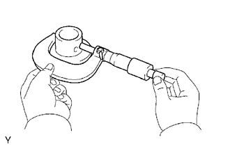
(b) Using a micrometer, measure the cam lobe height. Standard Cam Lobe Height:
Minimum Cam Lobe Height:
If the cam lobe height is less than the minimum, replace the camshaft. |
|
|
(c) Using a micrometer, measure the journal diameter. Standard Journal Diameter:
If the journal diameter is not as specified, check the oil clearance. |
|
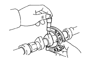
4. INSPECT CAMSHAFT TIMING GEAR ASSEMBLY
(a) Clamp the camshaft in a vise.
NOTICE:
Be careful not to damage the camshaft in the vise.
|
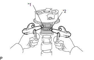
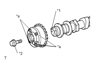
(b) Put the camshaft timing gear assembly and camshaft together by aligning the key groove and straight pin. Text in Illustration
|
|
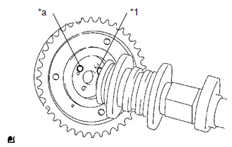
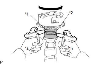
(c) Lightly press and turn the camshaft timing gear assembly against the camshaft, and press harder after the pin enters the groove.
NOTICE:
Be sure not to turn the camshaft timing gear assembly in the retard direction.
(d) Check that there is no clearance between the camshaft timing gear assembly flange and the camshaft.
|
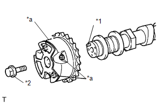
(e) Tighten the flange bolt while holding the camshaft. Torque: 100 N·m {1020 kgf·cm, 74 ft·lbf} |
|
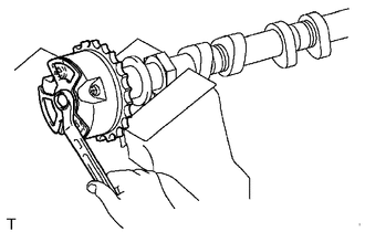
(f) Check the lock of the camshaft timing gear assembly.
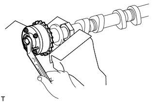
(1) Clamp the camshaft in a vise, and confirm that the camshaft timing gear assembly is locked.
NOTICE:
Be careful not to damage the camshaft.
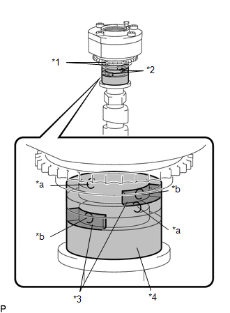
(g) Release the lock pin.
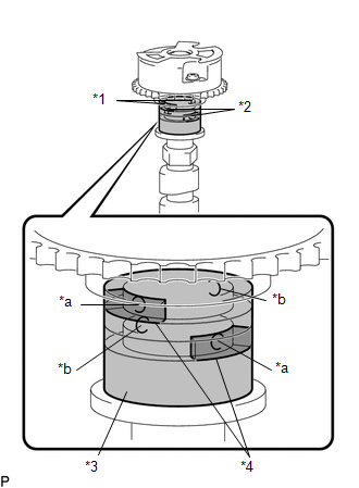
Text in Illustration
|
*1 |
Advance Side Path |
|
*2 |
Retard Side Path |
|
*3 |
Vinyl Tape |
|
*4 |
Rubber |
|
*a |
Close |
|
*b |
Open |
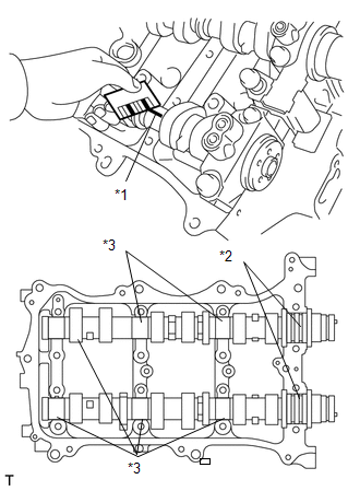
(1) Cover the 4 oil paths of the cam journal with vinyl tape as shown in the illustration.
HINT:
The 2 advance side paths are located in the camshaft groove. Plug one of the paths with a rubber piece.
(2) Break through the tape on the advance side path and the retard side path on the opposite side of the hole of the advance side path, as shown in the illustration.
|
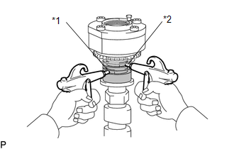
(3) Apply approximately 200 kPa (2.0 kgf/cm2, 29 psi) of air pressure to the 2 opened paths. Text in Illustration
CAUTION: Cover the paths with a piece of cloth when applying pressure to prevent oil from spraying. |
|
|
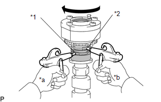
(4) Check that the camshaft timing gear assembly rotates in the advance direction when reducing the air pressure applied to the retard side path. Text in Illustration
HINT: This operation releases the lock pin at the most retarded position. |
|
(5) When the camshaft timing gear assembly reaches the most advanced position, release the air pressure first from the retard side path and next from the advance side path.
NOTICE:
Do not release the air pressure from the advance side path first. The gear may abruptly shift in the retard direction and break the lock pin.
(h) Check for smooth rotation.
(1) Turn the camshaft timing gear assembly within its movable range (21°) 2 or 3 times, but do not turn it to the most retarded position. Make sure that the gear turns smoothly.
NOTICE:
Do not use air pressure to perform the smooth operation check.
(i) Check the lock in the most retarded position.
(1) Confirm that the camshaft timing gear assembly locks at the most retarded position.
|
(j) Remove the flange bolt and camshaft timing gear assembly. Text in Illustration
NOTICE:
|
|
5. INSPECT CAMSHAFT TIMING EXHAUST GEAR ASSEMBLY
(a) Clamp the camshaft in a vise.
NOTICE:
Be careful not to damage the camshaft in the vise.
|
(b) Put the camshaft timing exhaust gear assembly and camshaft together by aligning the key groove and straight pin. Text in Illustration
|
|
(c) Lightly press and turn the camshaft timing gear assembly against the camshaft, and press harder after the pin enters the groove.
NOTICE:
Be sure not to turn the camshaft timing exhaust gear in the retard direction.
(d) Check that there is no clearance between the gear flange and the camshaft.
|
(e) Tighten the flange bolt while holding the camshaft. Torque: 100 N·m {1020 kgf·cm, 74 ft·lbf} |
|
(f) Check the camshaft timing exhaust gear lock.
(1) Make sure that the camshaft timing exhaust gear assembly locks.
(g) Release the lock pin.
Text in Illustration
|
*1 |
Retard Side Path |
|
*2 |
Advance Side Path |
|
*3 |
Rubber |
|
*4 |
Vinyl Tape |
|
*a |
Open |
|
*b |
Close |
(1) Cover the 4 oil paths of the cam journal with vinyl tape as shown in the illustration.
HINT:
The 2 advance side paths are located in the camshaft groove. Plug one of the paths with a rubber piece.
(2) Break through the tape on the advance side path and the retard side path on the opposite side of the hole of the advance side path, as shown in the illustration.
|
(3) Apply approximately 200 kPa (2.0 kgf/cm2, 29 psi) of air pressure to the 2 opened paths (the advance side path and the retard side path). Text in Illustration
CAUTION: Cover the paths with a piece of cloth when applying pressure to prevent oil from spraying. |
|
|
(4) Make sure that the camshaft timing exhaust gear assembly rotates in the retard direction when reducing the air pressure applied to the advance side path. Text in Illustration
HINT: The lock pin is released and the camshaft timing exhaust gear assembly turns in the retard direction. |
|
(5) When the camshaft timing exhaust gear assembly moves to the most retarded position, release the air pressure first from the advance side path, and then release the air pressure from the retard side path.
NOTICE:
Be sure to release the air pressure from the advance side path first. If the air pressure of the retard side path is released first, the camshaft timing exhaust gear assembly may abruptly shift in the advance direction and break the lock pin or other parts.
(h) Check for smooth rotation.
(1) Turn the camshaft timing exhaust gear assembly within its movable range (18.5°) 2 or 3 times, but do not turn it to the most advanced position. Make sure that the gear assembly turns smoothly.
NOTICE:
When the air pressure is released from the advance side path and then from the retard side path, the gear assembly automatically returns to the most advanced position due to the advance assist spring operation and locks. Gradually release the air pressure from the retard side path before performing the smooth rotation check.
(i) Check the lock at the most advanced position.
(1) Make sure that the camshaft timing exhaust gear assembly locks at the most advanced position.
|
(j) Remove the flange bolt and camshaft timing exhaust gear assembly. Text in Illustration
NOTICE:
|
|
6. INSPECT CYLINDER HEAD SET BOLT
|
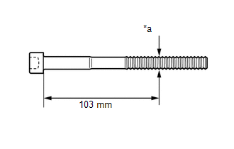
(a) Using a vernier caliper, measure the diameter of the threads at the measurement point. Text in Illustration
Standard diameter: 10.85 to 11.00 mm (0.4272 to 0.4330 in.) Minimum diameter: 10.70 mm (0.4212 in.) Measurement point (distance from the seat): 103 mm (4.06 in.) HINT:
|
|
7. INSPECT CHAIN SUB-ASSEMBLY
|
(a) Pull the chain sub-assembly with a force of 147 N (15 kgf, 33 lbf) as shown in the illustration. |
|
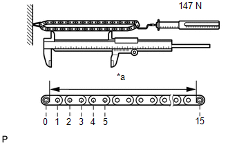
(b) Using a vernier caliper, measure the length of 15 links.
Text in Illustration
|
*a |
Measuring Point |
Maximum chain elongation:
136.9 mm (5.389 in.)
NOTICE:
Perform the measurement at 3 random places. Use the average of the measurements.
If the average elongation is greater than the maximum, replace the chain sub-assembly.
8. INSPECT NO. 2 CHAIN SUB-ASSEMBLY
|
(a) Pull the No. 2 chain sub-assembly with a force of 147 N (15 kgf, 33 lbf) as shown in the illustration. |
|
(b) Using a vernier caliper, measure the length of 15 links.
Text in Illustration
|
*a |
Measuring Point |
Maximum chain elongation:
137.6 mm (5.417 in.)
NOTICE:
Perform the measurement at 3 random places. Use the average of the measurements.
If the average elongation is greater than the maximum, replace the chain sub-assembly.
9. INSPECT CRANKSHAFT TIMING SPROCKET
(a) Place the chain around the sprocket.
|
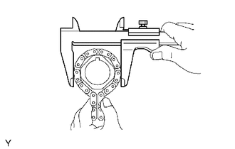
(b) Using a vernier caliper, measure the sprocket diameter with the chain sub-assembly. Minimum sprocket diameter (with chain): 61.4 mm (2.418 in.) HINT: The vernier caliper must contact the chain rollers for the measurement. If the diameter is less than the minimum, replace the chain and sprocket. |
|
10. INSPECT IDLE SPROCKET ASSEMBLY
(a) Place the chain around the sprocket.
|
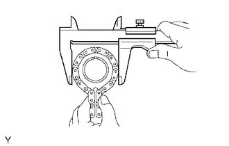
(b) Using a vernier caliper, measure the sprocket diameter with the chain. Minimum sprocket diameter (with chain): 61.4 mm (2.418 in.) HINT: The vernier caliper must contact the chain rollers for the measurement. If the diameter is less than the minimum, replace the chain and sprocket. |
|
11. INSPECT IDLE GEAR SHAFT OIL CLEARANCE
|
(a) Using a micrometer, measure the idle gear shaft diameter. Standard idle gear shaft diameter: 22.987 to 23.000 mm (0.9050 to 0.9055 in.) |
|
|
(b) Using a caliper gauge, measure the inside diameter of the idle sprocket assembly. Standard idle gear inside diameter: 23.020 to 23.030 mm (0.9063 to 0.9067 in.) |
|
(c) Subtract the idle gear shaft diameter measurement from the idle sprocket inside diameter measurement.
Standard oil clearance:
0.020 to 0.043 mm (0.000787 to 0.00169 in.)
Maximum oil clearance:
0.093 mm (0.00366 in.)
If the thrust oil clearance is greater than the maximum, replace the idle gear shaft and idle sprocket assembly.
12. INSPECT NO. 1 CHAIN TENSIONER ASSEMBLY
|
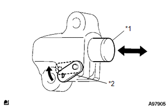
(a) Move the stopper plate upward to release the lock. Push the plunger and check that it moves smoothly. Text in Illustration
If necessary, replace the No. 1 chain tensioner assembly. |
|
13. INSPECT NO. 2 CHAIN TENSIONER ASSEMBLY
|
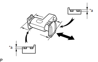
(a) Check that the plunger moves smoothly. Text in Illustration
|
|
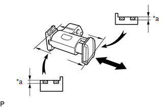
(b) Using a vernier caliper, measure the worn depth of the No. 2 chain tensioner assembly.
Maximum depth:
0.9 mm (0.0354 in.)
If the depth is greater than the maximum, replace the No. 2 chain tensioner assembly.
14. INSPECT NO. 3 CHAIN TENSIONER ASSEMBLY
|
(a) Check that the plunger moves smoothly. Text in Illustration
|
|
(b) Using a vernier caliper, measure the worn depth of the No. 3 chain tensioner assembly.
Maximum depth:
0.9 mm (0.0354 in.)
If the depth is greater than the maximum, replace the No. 3 chain tensioner assembly.
15. INSPECT CHAIN TENSIONER SLIPPER
|
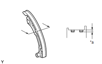
(a) Measure the worn depth of the chain tensioner slipper. Text in Illustration
Maximum depth: 1.0 mm (0.0394 in.) If the depth is greater than the maximum, replace the chain tensioner slipper. |
|
16. INSPECT NO. 1 CHAIN VIBRATION DAMPER
|
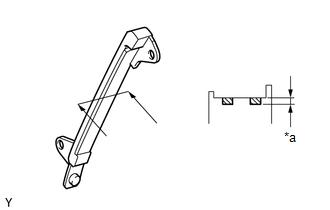
(a) Using a vernier caliper, measure the worn depth of the No. 1 chain vibration damper. Text in Illustration
Maximum depth: 1.0 mm (0.0394 in.) If the depth is greater than the maximum, replace the No. 1 chain vibration damper. |
|
17. INSPECT NO. 2 CHAIN VIBRATION DAMPER
|
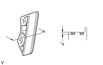
(a) Using a vernier caliper, measure the worn depth of the No. 2 chain vibration damper. Text in Illustration
Maximum depth: 1.0 mm (0.0394 in.) If the depth is greater than the maximum, replace the No. 2 chain vibration damper. |
|
18. INSPECT CAMSHAFT THRUST CLEARANCE
(a) Inspect the bank 1 camshaft thrust clearance.
(1) Install the bank 1 camshaft (See page
![2016 MY Sienna [12/2015 - 08/2016]; 2GR-FE ENGINE MECHANICAL: CAMSHAFT: INSTALLATION](/t3Portal/stylegraphics/info.gif) ).
).
|
(2) Using a dial indicator, measure the thrust clearance while moving the camshaft back and forth. Standard thrust clearance: 0.08 to 0.13 mm (0.00315 to 0.00512 in.) Maximum thrust clearance: 0.15 mm (0.00591 in.) If the thrust clearance is greater than the maximum, replace the camshaft housing. If the thrust surface is damaged, replace the camshaft. |
|
(b) Inspect the bank 2 camshaft thrust clearance.
(1) Install the bank 2 camshaft (See page
).
(2) Using a dial indicator, measure the thrust clearance while moving the camshaft back and forth.
Standard thrust clearance:
0.08 to 0.13 mm (0.00315 to 0.00512 in.)
Maximum thrust clearance:
0.15 mm (0.00591 in.)
If the thrust clearance is greater than the maximum, replace the camshaft housing. If the thrust surface is damaged, replace the camshaft.
19. INSPECT CAMSHAFT OIL CLEARANCE (for Bank 1)
(a) Clean the camshaft bearing caps, camshaft housing and camshaft journals.
(b) Place the camshafts on the camshaft housing.
|
(c) Lay a strip of Plastigage across each camshaft journal. Text in Illustration
|
|
(d) Install the camshaft bearing caps (See page
).
NOTICE:
Do not turn the camshaft.
(e) Remove the camshaft bearing caps (See page
).
|
(f) Measure the Plastigage at its widest point. Text in Illustration
Standard Oil Clearance:
Maximum Oil Clearance:
If the oil clearance is greater than the maximum, replace the camshaft. If necessary, replace the camshaft housing. |
|
20. INSPECT CAMSHAFT OIL CLEARANCE (for Bank 2)
(a) Clean the camshaft bearing caps, camshaft housing and camshaft journals.
(b) Place the camshafts on the camshaft housing.
|
(c) Lay a strip of Plastigage across each camshaft journal. Text in Illustration
|
|
(d) Install the camshaft bearing caps (See page
).
NOTICE:
Do not turn the camshaft.
(e) Remove the camshaft bearing caps (See page
).
|
(f) Measure the Plastigage at its widest point. Text in Illustration
Standard Oil Clearance:
Maximum Oil Clearance:
If the oil clearance is greater than the maximum, replace the camshaft. If necessary, replace the camshaft housing sub-assembly. |
|
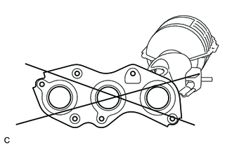
21. INSPECT EXHAUST MANIFOLD SUB-ASSEMBLY LH
|
(a) Using a precision straightedge and feeler gauge, measure the warpage on the contact surface of the cylinder head. Maximum warpage: 0.7 mm (0.0276 in.) HINT: The maximum allowable warpage of each installation surface is 0.3 mm (0.0118 in.). If the warpage is greater than the maximum, replace the manifold. |
|
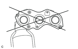
22. INSPECT EXHAUST MANIFOLD SUB-ASSEMBLY RH
|
(a) Using a precision straightedge and feeler gauge, measure the warpage on the contact surface of the cylinder head. Maximum warpage: 0.7 mm (0.0276 in.) HINT: The maximum allowable warpage of each installation surface is 0.3 mm (0.0118 in.). If the warpage is greater than the maximum, replace the manifold. |
|
23. INSPECT INTAKE MANIFOLD
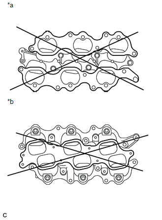
Text in Illustration
|
*a |
Cylinder Head Side |
|
*b |
Surge Tank Side |
(a) Cylinder head side:
(1) Using a precision straightedge and feeler gauge, measure the surface contacting the cylinder head for warpage.
Maximum warpage:
0.1 mm (0.00394 in.)
If the warpage is greater than the maximum, replace the intake manifold.
(b) Surge tank side:
(1) Using a precision straightedge and feeler gauge, measure the surface contacting the surge tank for warpage.
Maximum warpage:
0.1 mm (0.00394 in.)
If the warpage is greater than the maximum, replace the intake manifold.
|
|
|