| Last Modified: 08-28-2024 | 6.11:8.1.0 | Doc ID: RM100000000VICW |
| Model Year Start: 2016 | Model: Sienna | Prod Date Range: [12/2015 - 08/2016] |
| Title: 2GR-FE ENGINE MECHANICAL: ENGINE UNIT: INSTALLATION; 2016 MY Sienna [12/2015 - 08/2016] | ||
INSTALLATION
PROCEDURE
1. INSTALL ENGINE COOLANT TEMPERATURE SENSOR
2. INSTALL KNOCK SENSOR
3. INSTALL KNOCK SENSOR WIRE
(a) Connect the 2 clamps, 2 knock sensor connectors and knock sensor wire connector.
4. INSTALL ENGINE OIL PRESSURE SWITCH ASSEMBLY
|
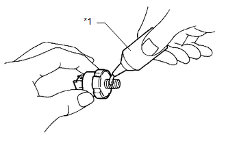
(a) Clean the threads of the oil pressure switch. Apply adhesive to 2 or 3 threads of the oil pressure switch assembly. Text in Illustration
Adhesive: Toyota Genuine Adhesive 1344, Three Bond 1344 or equivalent |
|
(b) Using a deep socket wrench, install the oil pressure switch.
Torque:
15 N·m {153 kgf·cm, 11 ft·lbf}
NOTICE:
Do not start the engine within 1 hour after installation to prevent oil leaks.
5. INSTALL NO. 1 VACUUM SWITCHING VALVE ASSEMBLY
(a) Install the No. 1 vacuum switching valve with the bolt.
Torque:
10 N·m {102 kgf·cm, 7 ft·lbf}
6. INSTALL WATER PUMP PULLEY
7. INSTALL NO. 2 IDLER PULLEY SUB-ASSEMBLY
(a) Install the idler pulley cover plate, No. 2 idler pulley sub-assembly and No. 2 idler pulley cover plate with the bolt.
Torque:
54 N·m {550 kgf·cm, 40 ft·lbf}
8. INSTALL NO. 2 TIMING GEAR COVER
(a) Install the No. 2 timing gear cover with the 2 bolts.
Torque:
6.0 N·m {61 kgf·cm, 53 in·lbf}
9. INSTALL V-RIBBED BELT TENSIONER ASSEMBLY
|
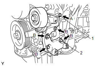
(a) Temporarily install the V-ribbed belt tensioner assembly with the 5 bolts. HINT: Each bolt length is as follows: A: 70 mm (2.76 in.) B: 33 mm (1.30 in.) |
|
(b) Install the V-ribbed belt tensioner assembly by tightening the bolt 1 and bolt 2 in the order shown in the illustration.
Torque:
43 N·m {438 kgf·cm, 32 ft·lbf}
(c) Tighten the other bolts.
Torque:
43 N·m {438 kgf·cm, 32 ft·lbf}
10. INSTALL EXHAUST MANIFOLD SUB-ASSEMBLY LH
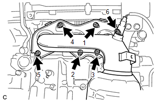
(a) Install a new gasket as shown in the illustration.
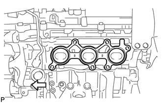
Text in Illustration

|
Engine Front |
|
(b) Install the exhaust manifold sub-assembly LH with the 6 nuts in the order shown in the illustration. Torque: 21 N·m {214 kgf·cm, 15 ft·lbf} |
|
11. INSTALL NO. 2 EXHAUST MANIFOLD HEAT INSULATOR
12. INSTALL NO. 2 MANIFOLD STAY
13. INSTALL NO. 2 ENGINE OIL LEVEL DIPSTICK GUIDE
(a) Install a new O-ring to the No. 2 engine oil level dipstick guide.
(b) Apply a light coat of engine oil to the O-ring.
(c) Push in the No. 2 engine oil level dipstick guide end into the engine oil level dipstick guide.
(d) Install the No. 2 engine oil level dipstick guide with the bolt.
Torque:
21 N·m {214 kgf·cm, 15 ft·lbf}
(e) Install the engine oil level dipstick.
14. INSTALL EXHAUST MANIFOLD SUB-ASSEMBLY RH
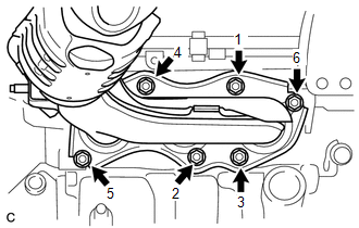
(a) Install a new gasket as shown in the illustration.
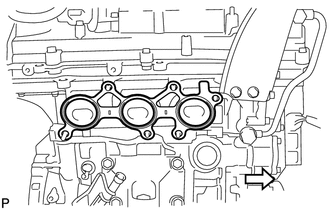
Text in Illustration

|
Engine Front |
|
(b) Install the exhaust manifold sub-assembly RH with the 6 nuts in the order shown in the illustration. Torque: 21 N·m {214 kgf·cm, 15 ft·lbf} |
|
15. INSTALL INTAKE MANIFOLD
NOTICE:
DO NOT apply oil to the bolts listed below:
|
Tightening Part |
|---|
|
Intake Manifold and Cylinder Head Sub-assembly RH |
|
Intake Manifold and Cylinder Head Sub-assembly LH |
(a) Set a new gasket on each cylinder head.
NOTICE:
- Align the port holes of the gasket and cylinder head.
- Make sure that the gasket is installed in the correct direction.
(b) Set the intake manifold on the cylinder heads.
(c) Install and tighten the 6 bolts and 4 nuts uniformly in several steps.
Torque:
21 N·m {214 kgf·cm, 15 ft·lbf}
16. INSTALL FUEL HOSE PROTECTOR
(a) Install the fuel hose protector with the 2 bolts and nut.
Torque:
Bolt :
21 N·m {214 kgf·cm, 15 ft·lbf}
Nut :
10 N·m {102 kgf·cm, 7 ft·lbf}
17. INSTALL NO. 2 ENGINE MOUNTING STAY RH
(a) Install the No. 2 engine mounting stay RH with the bolt.
Torque:
21 N·m {214 kgf·cm, 15 ft·lbf}
18. INSTALL IGNITION COIL ASSEMBLY
19. INSTALL NO. 1 SURGE TANK STAY
(a) Install the No. 1 surge tank stay with the bolt.
Torque:
21 N·m {214 kgf·cm, 15 ft·lbf}
20. INSTALL THROTTLE BODY BRACKET
(a) Install the throttle body bracket with the bolt.
Torque:
21 N·m {214 kgf·cm, 15 ft·lbf}
21. INSTALL INTAKE AIR SURGE TANK ASSEMBLY
22. INSTALL ENGINE HANGERS
(a) Install the 2 engine hangers with the 4 bolts as shown in the illustration.
Part No.
|
Item |
Part No. |
|---|---|
|
No. 1 engine hanger |
12281-31120 |
|
No. 2 engine hanger |
12282-31100 |
|
Bolt |
91671-10825 |
Torque:
33 N·m {337 kgf·cm, 24 ft·lbf}
(b) Attach the engine sling device and hang the engine with the chain block.
23. REMOVE ENGINE STAND
|
|
|
![2016 MY Sienna [12/2015 - 08/2016]; 2GR-FE (ENGINE CONTROL): ENGINE COOLANT TEMPERATURE SENSOR: INSTALLATION+](/t3Portal/stylegraphics/info.gif)
