- Open or short in air fuel ratio sensor (bank 1, 2 sensor 1) circuit
- Air fuel ratio sensor (bank 1, 2 sensor 1)
- ECM
| Last Modified: 08-28-2024 | 6.11:8.1.0 | Doc ID: RM100000000VICD |
| Model Year Start: 2016 | Model: Sienna | Prod Date Range: [12/2015 - 08/2016] |
| Title: 2GR-FE (ENGINE CONTROL): SFI SYSTEM: P2237-P2239,P2240-P2242,P2252,P2253,P2255,P2256; Oxygen (A/F) Sensor Pumping Current Circuit / Open (for A/F sensor) (Bank 1 Sensor 1); 2016 MY Sienna [12/2015 - 08/2016] | ||
|
DTC |
P2237 |
Oxygen (A/F) Sensor Pumping Current Circuit / Open (for A/F sensor) (Bank 1 Sensor 1) |
|
DTC |
P2238 |
Oxygen Sensor Pumping Current Circuit Low (for A/F sensor) (Bank 1 Sensor 1) |
|
DTC |
P2239 |
Oxygen Sensor Pumping Current Circuit High (for A/F sensor) (Bank 1 Sensor 1) |
|
DTC |
P2240 |
Oxygen (A/F) Sensor Pumping Current Circuit / Open (for A/F sensor) (Bank 2 Sensor 1) |
|
DTC |
P2241 |
Oxygen Sensor Pumping Current Circuit Low (for A/F sensor) (Bank 2 Sensor 1) |
|
DTC |
P2242 |
Oxygen Sensor Pumping Current Circuit High (for A/F sensor) (Bank 2 Sensor 1) |
|
DTC |
P2252 |
Oxygen Sensor Reference Ground Circuit Low (for A/F sensor) (Bank 1 Sensor 1) |
|
DTC |
P2253 |
Oxygen Sensor Reference Ground Circuit High (for A/F sensor) (Bank 1 Sensor 1) |
|
DTC |
P2255 |
Oxygen Sensor Reference Ground Circuit Low (for A/F sensor) (Bank 2 Sensor 1) |
|
DTC |
P2256 |
Oxygen Sensor Reference Ground Circuit High (for A/F sensor) (Bank 2 Sensor 1) |
DESCRIPTION
HINT:
- Although the DTC titles include oxygen sensor, these DTCs relate to the air fuel ratio sensor.
- Sensor 1 refers to the sensor mounted in front of the three-way catalytic converter and located near the engine assembly.
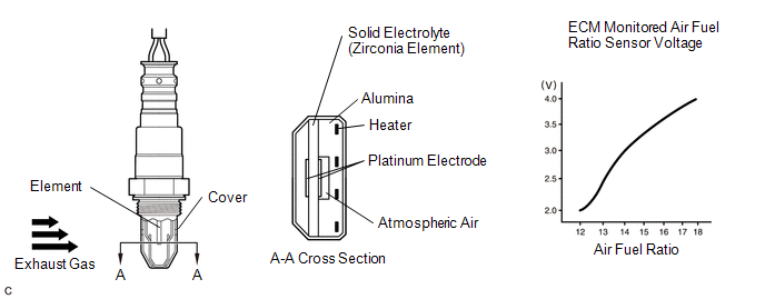
The air fuel ratio sensor generates voltage* that corresponds to the actual air fuel ratio. This sensor voltage is used to provide the ECM with feedback so that it can control the air fuel ratio. The ECM determines the deviation from the stoichiometric air fuel ratio level, and regulates the fuel injection duration. If the air fuel ratio sensor malfunctions, the ECM is unable to control the air fuel ratio accurately.
The air fuel ratio sensor is a planar type with an integrated heater, which heats the solid electrolyte (zirconia element). This heater is controlled by the ECM. When the intake air volume is low (the exhaust gas temperature is low), current flows to the heater to heat the sensor, in order to facilitate accurate oxygen concentration detection. In addition, the sensor and heater portions are narrower than the conventional type. The heat generated by the heater is conducted to the solid electrolyte through the alumina, and therefore the sensor activation is accelerated.
A three-way catalytic converter is used in order to convert the carbon monoxide (CO), hydrocarbon (HC), and nitrogen oxides (NOx) into less harmful substances. To allow the three-way catalytic converter to function effectively, it is necessary to keep the air fuel ratio of the engine near the stoichiometric air fuel ratio.
*: Value changes inside the ECM. Since the air fuel ratio sensor uses a current output element, the current is converted to a voltage inside the ECM. Any measurements taken at the air fuel ratio sensor or ECM connectors will show a constant voltage.
|
DTC No. |
DTC Detection Condition |
Trouble Area |
|---|---|---|
|
P2237 P2240 |
Open in the circuit between terminals A1A+ (A2A+) and A1A- (A2A-) of the air fuel ratio sensor while engine running (2 trip detection logic) |
|
|
P2238 P2241 |
Condition (a) or (b) continues for 5.0 seconds or more (2 trip detection logic): (a) Voltage at terminal A1A+ (A2A+) is 0.5 V or less (b) Voltage difference between terminals A1A+ (A2A+) and A1A- (A2A-) is 0.1 V or less for 10 seconds
Air fuel ratio sensor admittance: Less than 0.0074 1/Ω (2 trip detection logic) |
|
|
P2239 P2242 |
A1A+ (A2A+) voltage is more than 4.5 V for 5.0 seconds or more (2 trip detection logic) |
|
|
P2252 P2255 |
A1A- (A2A-) voltage is 0.5 V or less for 5.0 seconds or more (2 trip detection logic) |
|
|
P2253 P2256 |
A1A- (A2A-) voltage is more than 4.5 V for 5.0 seconds or more (2 trip detection logic) |
|
HINT:
- DTCs P2237, P2238, P2239, P2252 and P2253 indicate malfunctions related to the bank 1 air fuel ratio sensor circuit.
- DTCs P2240, P2241, P2242, P2255 and P2256 indicate malfunctions related to the bank 2 air fuel ratio sensor circuit.
MONITOR DESCRIPTION
The air fuel ratio sensor varies its output voltage in proportion to the air fuel ratio. If the air fuel ratio sensor impedance (alternating current resistance) or voltage output deviates greatly from the standard range, the ECM determines that there is an open or short in the air fuel ratio sensor circuit.
MONITOR STRATEGY
|
Related DTCs |
P2237: Air fuel ratio sensor (bank 1 sensor 1) open circuit between A1A+ and A1A- P2238: Air fuel ratio sensor (bank 1 sensor 1) short circuit between A1A+ and A1A- P2238: Air fuel ratio sensor (bank 1 sensor 1) short circuit between A1A+ and GND P2238: Air fuel ratio sensor (bank 1 sensor 1) low admittance P2239: Air fuel ratio sensor (bank 1 sensor 1) short circuit between A1A+ and +B P2240: Air fuel ratio sensor (bank 2 sensor 1) open circuit between A2A+ and A2A- P2241: Air fuel ratio sensor (bank 2 sensor 1) short circuit between A2A+ and A2A- P2241: Air fuel ratio sensor (bank 2 sensor 1) short circuit between A2A+ and GND P2241: Air fuel ratio sensor (bank 2 sensor 1) low admittance P2242: Air fuel ratio sensor (bank 2 sensor 1) short circuit between A2A+ and +B P2252: Air fuel ratio sensor (bank 1 sensor 1) short circuit between A1A- and GND P2253: Air fuel ratio sensor (bank 1 sensor 1) short circuit between A1A- and +B P2255: Air fuel ratio sensor (bank 2 sensor 1) short circuit between A2A- and GND P2256: Air fuel ratio sensor (bank 2 sensor 1) short circuit between A2A- and +B |
|
Required Sensors / Components (Main) |
Air fuel ratio sensor (bank 1, 2 sensor 1) |
|
Required Sensors / Components (Related) |
Engine coolant temperature sensor, crankshaft position sensor |
|
Frequency of Operation |
Continuous |
|
Duration |
P2237 and P2240: 10 seconds P2238 and P2241 (air fuel ratio sensor low admittance): 10 seconds Others: 5 seconds |
|
MIL Operation |
2 driving cycles |
|
Sequence of Operation |
None |
TYPICAL ENABLING CONDITIONS
|
Monitor runs whenever following DTCs are not present |
P0016, P0018 (VVT system bank 1, 2 - misalignment) P0017, P0019 (Exhaust VVT system bank 1, 2 - misalignment) P0031, P0032, P0051, P0052, P101D, P103D (Air fuel ratio sensor heater) P0102, P0103 (Mass air flow meter) P0112, P0113 (Intake air temperature sensor) P0115, P0117, P0118 (Engine coolant temperature sensor) P0120, P0121, P0122, P0123, P0220, P0222, P0223, P2135 (Throttle position sensor) P0125 (Insufficient engine coolant temperature for closed loop) P0128 (Thermostat) P0171, P0172, P0174, P0175 (Fuel system) P0300, P0301, P0302, P0303, P0304, P0305, P0306 (Misfire) P0335 (Crankshaft position sensor) P0451, P0452, P0453 (Evaporative emission control system) P0500 (Vehicle speed sensor) P0505 (Idle speed control) P219A, P219B, P219C, P219D, P219E, P219F, P21A0, P21A1 (Air-fuel ratio imbalance) |
P2237 and P2240 (Air fuel ratio sensor open circuit between A1A+ and A1A-/A2A+ and A2A-)
|
Estimated sensor temperature |
450 to 550°C (842 to 1022°F) |
|
Engine |
Running |
|
Battery voltage |
11 V or higher |
|
Ignition switch |
ON |
|
Time after ignition switch is OFF to ON |
5 seconds or more |
P2238 and P2241 (Low admittance)
|
Estimated sensor temperature |
700 to 800°C (1292 to 1472°F) |
|
Engine coolant temperature |
5°C (41°F) or more (varies with engine coolant temperature at engine start) |
|
Fuel cut |
Not executed |
Others
|
Battery voltage |
11 V or higher |
|
Ignition switch |
ON |
|
Time after ignition switch is off to ON |
5 seconds or more |
TYPICAL MALFUNCTION THRESHOLDS
P2237 and P2240 (Open circuit between A1A+ and A1A-/A2A+ and A2A-)
|
Air fuel ratio sensor admittance |
Less than 0.0018 1/Ω |
P2238 and P2241 (Low admittance)
|
Air fuel ratio sensor admittance |
Less than 0.0054 1/Ω |
P2238 and P2241 (Short circuit between A1A+ and GND/A2A+ and GND)
|
A1A+/A2A+ terminal voltage |
0.5 V or less |
P2238 and P2241 (Short circuit between A1A+ and A1A-/A2A+ and A2A-)
|
Difference between A1A+ and A1A-/A2A+ and A2A- terminal voltage |
0.1 V or less |
P2239 and P2242 (Short circuit between A1A+ and +B/A2A+ and +B)
|
A1A+/A2A+ terminal voltage |
Higher than 4.5 V |
P2252 and P2255 (Short circuit between A1A- and GND/A2A- and GND)
|
A1A-/A2A- terminal voltage |
0.5 V or less |
P2253 and P2256 (Short circuit between A1A- and +B/A2A- and +B)
|
A1A-/A2A- terminal voltage |
Higher than 4.5 V |
CONFIRMATION DRIVING PATTERN
- Connect the Techstream to the DLC3.
- Turn the ignition switch to ON and turn the Techstream on.
-
Clear DTCs (even if no DTCs are stored, perform the clear DTC procedure) (See page
![2016 MY Sienna [12/2015 - 08/2016]; 2GR-FE (ENGINE CONTROL): SFI SYSTEM: DTC CHECK / CLEAR](/t3Portal/stylegraphics/info.gif) ).
).
- Turn the ignition switch off and wait for at least 30 seconds.
- Turn the ignition switch to ON and turn the Techstream on.
- Start the engine and wait 2 minutes.
- Enter the following menus: Powertrain / Engine / Trouble Codes.
-
Read pending DTCs.
HINT:
- If a pending DTC is output, the system is malfunctioning.
- If a pending DTC is not output, perform the following procedure.
- Enter the following menus: Powertrain / Engine / Utility / All Readiness.
- Input the DTC: P2237, P2238, P2239, P2240, P2241, P2242, P2252, P2253, P2255 or P2256.
-
Check the DTC judgment result.
Techstream Display
Description
NORMAL
- DTC judgment completed
- System normal
ABNORMAL
- DTC judgment completed
- System abnormal
INCOMPLETE
- DTC judgment not completed
- Perform driving pattern after confirming DTC enabling conditions
N/A
- Unable to perform DTC judgment
- Number of DTCs which do not fulfill DTC preconditions has reached ECU memory limit
HINT:
- If the judgment result shows ABNORMAL, the system has a malfunction.
- If the judgment result shows INCOMPLETE or N/A, idle the engine for 3 minutes and check the DTC judgment result again.
-
If no pending DTC is output, perform a universal trip and check for permanent DTCs (See page
).
HINT:
- If a permanent DTC is output, the system is malfunctioning.
- If no permanent DTC is output, the system is normal.
WIRING DIAGRAM
Refer to DTC P2195 (See page
).
CAUTION / NOTICE / HINT
NOTICE:
Inspect the fuses for circuits related to this system before performing the following inspection procedure.
HINT:
-
Refer to "Data List / Active Test" [AFS Voltage B1S1 and AFS Voltage B2S1] (See page
).
- Read freeze frame data using the Techstream. The ECM records vehicle and driving condition information as freeze frame data the moment a DTC is stored. When troubleshooting, freeze frame data can help determine if the vehicle was moving or stationary, if the engine was warmed up or not, if the air fuel ratio was lean or rich, and other data from the time the malfunction occurred.
-
Bank 1 refers to the bank that includes the No. 1 cylinder*.
*: The No. 1 cylinder is the cylinder which is farthest from the transaxle.
- Bank 2 refers to the bank that does not include the No. 1 cylinder.
- Sensor 1 refers to the sensor closest to the engine assembly.
- Sensor 2 refers to the sensor farthest away from the engine assembly.
PROCEDURE
|
1. |
CHECK HARNESS AND CONNECTOR (AIR FUEL RATIO SENSOR - ECM) |
(a) Disconnect the B13 and B14 air fuel ratio sensor connectors.
(b) Disconnect the B1 ECM connector.
(c) Measure the resistance according to the value(s) in the table below.
Standard Resistance:
|
Tester Connection |
Condition |
Specified Condition |
|---|---|---|
|
B14-1 (HA1A) - B1-22 (HA1A) |
Always |
Below 1 Ω |
|
B14-3 (A1A+) - B1-126 (A1A+) |
Always |
Below 1 Ω |
|
B14-4 (A1A-) - B1-125 (A1A-) |
Always |
Below 1 Ω |
|
B13-1 (HA2A) - B1-20 (HA2A) |
Always |
Below 1 Ω |
|
B13-3 (A2A+) - B1-103 (A2A+) |
Always |
Below 1 Ω |
|
B13-4 (A2A-) - B1-102 (A2A-) |
Always |
Below 1 Ω |
|
B14-1 (HA1A) or B1-22 (HA1A) - Body ground |
Always |
10 kΩ or higher |
|
B14-3 (A1A+) or B1-126 (A1A+) - Body ground |
Always |
10 kΩ or higher |
|
B14-4 (A1A-) or B1-125 (A1A-) - Body ground |
Always |
10 kΩ or higher |
|
B13-1 (HA2A) or B1-20 (HA2A) - Body ground |
Always |
10 kΩ or higher |
|
B13-3 (A2A+) or B1-103 (A2A+) - Body ground |
Always |
10 kΩ or higher |
|
B13-4 (A2A-) or B1-102 (A2A-) - Body ground |
Always |
10 kΩ or higher |
| NG |

|
REPAIR OR REPLACE HARNESS OR CONNECTOR |
|

|
2. |
REPLACE AIR FUEL RATIO SENSOR |
(a) Replace the air fuel ratio sensor (See page
).
HINT:
Perform "Inspection After Repair" after replacing the air fuel ratio sensor (See page
).
|
|
3. |
CHECK WHETHER DTC OUTPUT RECURS |
(a) Connect the Techstream to the DLC3.
(b) Turn the ignition switch to ON.
(c) Turn the Techstream on.
(d) Clear the DTCs (See page
).
(e) Turn the ignition switch off and wait for at least 30 seconds.
(f) Turn the ignition switch to ON and turn the Techstream on.
(g) Start the engine and warm it up.
(h) Drive the vehicle in accordance with the driving pattern described in the Confirmation Driving Pattern.
(i) Enter the following menus: Powertrain / Engine / Utility / All Readiness.
(j) Input the DTC: P2237, P2238, P2239, P2240, P2241, P2242, P2252, P2253, P2255 or P2256.
(k) Check the DTC judgment result.
Result
|
Result |
Proceed to |
|---|---|
|
NORMAL (DTC is not output) |
A |
|
ABNORMAL (DTC P2237, P2238, P2239, P2240, P2241, P2242, P2252, P2253, P2255 or P2256 is output) |
B |
| A |
|
END |
| B |
|
|
|
|