- Air fuel ratio sensor (bank 1, 2 sensor 1)
- Air fuel ratio sensor (bank 1, 2 sensor 1) heater
- ECM
| Last Modified: 08-28-2024 | 6.11:8.1.0 | Doc ID: RM100000000VICA |
| Model Year Start: 2016 | Model: Sienna | Prod Date Range: [12/2015 - 08/2016] |
| Title: 2GR-FE (ENGINE CONTROL): SFI SYSTEM: P014C-P014F,P015A-P015D; A/F Sensor Slow Response - Rich to Lean Bank 1 Sensor 1; 2016 MY Sienna [12/2015 - 08/2016] | ||
|
DTC |
P014C |
A/F Sensor Slow Response - Rich to Lean Bank 1 Sensor 1 |
|
DTC |
P014D |
A/F Sensor Slow Response - Lean to Rich Bank 1 Sensor 1 |
|
DTC |
P014E |
A/F Sensor Slow Response - Rich to Lean Bank 2 Sensor 1 |
|
DTC |
P014F |
A/F Sensor Slow Response - Lean to Rich Bank 2 Sensor 1 |
|
DTC |
P015A |
A/F Sensor Delayed Response - Rich to Lean Bank 1 Sensor 1 |
|
DTC |
P015B |
A/F Sensor Delayed Response - Lean to Rich Bank 1 Sensor 1 |
|
DTC |
P015C |
A/F Sensor Delayed Response - Rich to Lean Bank 2 Sensor 1 |
|
DTC |
P015D |
A/F Sensor Delayed Response - Lean to Rich Bank 2 Sensor 1 |
DESCRIPTION
HINT:
-
Refer to DTC P2195 (See page
![2016 MY Sienna [12/2015 - 08/2016]; 2GR-FE (ENGINE CONTROL): SFI SYSTEM: P2195-P2198; Oxygen (A/F) Sensor Signal Stuck Lean (Bank 1 Sensor 1)+](/t3Portal/stylegraphics/info.gif) ).
).
- Sensor 1 refers to the sensor mounted in front of the three-way catalytic converter and located near the engine assembly.
|
DTC No. |
DTC Detection Condition |
Trouble Area |
|---|---|---|
|
P014C P014E |
The "Rich to Lean response rate deterioration level*" value is standard or less. (2 trip detection logic) |
|
|
P014D P014F |
The "Lean to Rich response rate deterioration level*" value is standard or more. (2 trip detection logic) |
|
|
P015A P015C |
The "Rich to Lean delay level*" value is standard or more. (2 trip detection logic) |
|
|
P015B P015D |
The "Lean to Rich delay level*" value is standard or more. (2 trip detection logic) |
*: Calculated by ECM based on the air fuel ratio sensor output.
MONITOR DESCRIPTION
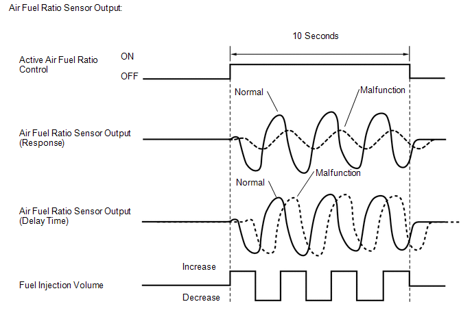
After the engine is warm, the ECM carries out air fuel ratio feedback control, and maintains the air fuel ratio at the theoretical level. In addition, after all the preconditions have been met, active air fuel ratio control is carried out for approx. 10 seconds, and during active air fuel ratio control, the ECM measures the response of the air fuel ratio sensor by increasing or decreasing a specific injection volume based on the theoretical air fuel ratio learned during normal air fuel control. The ECM determines whether there is an air fuel ratio sensor malfunction at the mid-point of active air fuel ratio control.
If the air fuel ratio sensor response ability is reduced, DTC P014C, P014D, P014E and P014F are output.
If the time it takes the air fuel ratio sensor output to change is delayed, DTC P015A, P015B, P015C and P015D are output.
MONITOR STRATEGY
|
Related DTCs |
P014C: Air fuel ratio sensor (bank 1) response rate (rich to lean response rate) P014D: Air fuel ratio sensor (bank 1) response rate (lean to rich response rate) P014E: Air fuel ratio sensor (bank 2) response rate (rich to lean response rate) P014F: Air fuel ratio sensor (bank 2) response rate (lean to rich response rate) P015A: Air fuel ratio sensor (bank 1) response rate (rich to lean delay) P015B: Air fuel ratio sensor (bank 1) response rate (lean to rich delay) P015C: Air fuel ratio sensor (bank 2) response rate (rich to lean delay) P015D: Air fuel ratio sensor (bank 2) response rate (lean to rich delay) |
|
Required Sensors/Components (Main) |
Air fuel ratio sensor (bank 1, 2 sensor 1) |
|
Required Sensors/Components (Related) |
Vehicle speed sensor, crankshaft position sensor |
|
Frequency of Operation |
Once per driving cycle |
|
Duration |
10 to 15 seconds |
|
MIL Operation |
2 driving cycles |
|
Sequence of Operation |
None |
TYPICAL ENABLING CONDITIONS
|
Monitor runs whenever following DTCs are not stored |
None |
|
Active air fuel ratio control |
Performing |
|
Active air fuel ratio control is performed when the following conditions are met |
- |
|
Battery voltage |
11 V or higher |
|
Engine coolant temperature |
75°C (167°F) or more |
|
Idle |
OFF |
|
Engine speed |
1000 rpm or more, and less than 3000 rpm |
|
Air fuel ratio sensor status |
Activated |
|
Fuel-cut |
OFF |
|
Engine load |
10% or more, and less than 70% |
|
Shift position |
2nd or higher |
|
Catalyst monitor |
Not yet |
|
Mass air flow |
5 g/sec. or more, and less than 10 g/sec. |
TYPICAL MALFUNCTION THRESHOLDS
P014C and P014E: Air Fuel Ratio Sensor (Bank 1, 2) Response Rate (Rich to Lean Response Rate)
|
Rich to Lean Response rate deterioration level |
0.038 V or less |
P014D and P014F: Air Fuel Ratio Sensor (Bank 1, 2) Response Rate (Lean to Rich Response Rate)
|
Lean to Rich Response rate deterioration level |
-0.038 V or higher |
P015A and P015C: Air Fuel Ratio Sensor (Bank 1, 2) Response Rate (Rich to Lean Delay)
|
Rich to Lean delay level |
230 msec. or more |
P015B and P015D: Air Fuel Ratio Sensor (Bank 1, 2) Response Rate (Lean to Rich Delay)
|
Lean to Rich delay level |
230 msec. or more |
MONITOR RESULT
Refer to Checking Monitor Status (See page
).
CONFIRMATION DRIVING PATTERN
HINT:
Performing this confirmation pattern will activate the air fuel ratio sensor response monitor.
- Connect the Techstream to the DLC3.
- Turn the ignition switch to ON.
- Turn the Techstream on.
-
Clear the DTCs (even if no DTCs are stored, perform the clear DTC procedure) (See page
).
- Turn the ignition switch off and wait for at least 30 seconds.
- Turn the ignition switch to ON and turn the Techstream on.
- Enter the following menus: Powertrain / Engine / Monitor / Current Monitor.
-
Check the monitor item O2 Sensor is incomplete.
HINT:
The test values for the test items RL RES RATE B1S1, LR RES RATE B1S1, RL DELAY B1S1, LR DELAY B1S1, RL RES RATE B2S1, LR RES RATE B2S1, RL DELAY B2S1 and LR DELAY B2S1 do not exist in the Detail of O2 Sensor monitor at this time (the initial value of "0.000" is indicated in each test item).
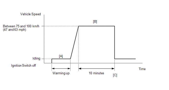
- Start the engine and warm it up (until the engine coolant temperature is 75°C (167°F) or higher) [A].
-
Drive the vehicle at a constant speed between 75 and 100 km/h (47 and 63 mph) for 10 minutes [B].
CAUTION:
When performing the confirmation driving pattern, obey all speed limits and traffic laws.
-
Check that the monitor item O2 Sensor becomes Complete.
HINT:
Check the test values on the Techstream by entering the following menus: Powertrain / Engine / Monitor / O2 Sensor / Details / RL RES RATE B1S1, LR RES RATE B1S1, RL DELAY B1S1, LR DELAY B1S1, RL RES RATE B2S1, LR RES RATE B2S1, RL DELAY B2S1 and LR DELAY B2S1.
-
If the monitor item O2 Sensor does not become Complete (if the test values indicated on the Techstream do not change), perform Readiness Monitor Drive Pattern for the A/F sensor and heated oxygen sensor (See page
).
- Enter the following menus: Powertrain / Engine / Trouble Codes.
- Read pending DTC [C].
-
If a pending DTC is output, the system is malfunctioning.
HINT:
If a pending DTC is not output, perform the following procedure.
- Enter the following menus: Powertrain / Engine / Utility / All Readiness.
- Input the DTC: P014C, P014D, P014E, P014F, P015A, P015B, P015C or P015D.
-
Check the DTC judgment result.
Techstream Display
Description
NORMAL
- DTC judgment completed
- System normal
ABNORMAL
- DTC judgment completed
- System abnormal
INCOMPLETE
- DTC judgment not completed
- Perform driving pattern after confirming DTC enabling conditions
N/A
- Unable to perform DTC judgment
- Number of DTCs which do not fulfill DTC preconditions has reached ECU memory limit
HINT:
- If the judgment result shows ABNORMAL, the system has a malfunction.
- If the judgment result shows NORMAL, the system is normal.
- If the judgment result shows INCOMPLETE or N/A, perform step [B] again.
- Enter the following menus: Powertrain / Engine / Utility / All Readiness.
-
Check the judgment result.
HINT:
- If the judgment result shows ABNORMAL, the system has a malfunction.
- If the judgment result shows NORMAL, the system is normal.
-
If the test result is INCOMPLETE or N/A and no pending DTC is output, perform a universal trip and check for permanent DTCs (See page
).
HINT:
- If a permanent DTC is output, the system is malfunctioning.
- If no permanent DTC is output, the system is normal.
WIRING DIAGRAM
Refer to DTC P2195 (See page
).
CAUTION / NOTICE / HINT
NOTICE:
Inspect the fuses for circuits related to this system before performing the following inspection procedure.
HINT:
- A low air fuel ratio sensor voltage could be caused by a rich air fuel mixture. Check for conditions that would cause the engine to run rich.
- A high air fuel ratio sensor voltage could be caused by a lean air fuel mixture. Check for conditions that would cause the engine to run lean.
- Read freeze frame data using the Techstream. The ECM records vehicle and driving condition information as freeze frame data the moment a DTC is stored. When troubleshooting, freeze frame data can be helpful in determining whether the vehicle was running or stopped, whether the engine was warmed up or not, whether the air fuel ratio was lean or rich, as well as other data recorded at the time of a malfunction.
-
Bank 1 refers to the bank that includes the No. 1 cylinder*.
*: The No. 1 cylinder is the cylinder which is farthest from the transaxle.
- Bank 2 refers to the bank that does not include the No. 1 cylinder.
- Sensor 1 refers to the sensor closest to the engine assembly.
- Sensor 2 refers to the sensor farthest away from the engine assembly.
PROCEDURE
|
1. |
CHECK ANY OTHER DTCS OUTPUT (DTC P014C, P014D, P014E, P014F, P015A, P015B, P015C OR P015D) |
(a) Connect the Techstream to the DLC3.
(b) Turn the ignition switch to ON.
(c) Turn the Techstream on.
(d) Enter the following menus: Powertrain / Engine / Trouble Codes.
(e) Read the DTCs.
Result
|
Result |
Proceed to |
|---|---|
|
DTC P014C, P014D, P014E, P014F, P015A, P015B, P015C or P015D is output |
A |
|
DTC P014C, P014D, P014E, P014F, P015A, P015B, P015C or P015D and other DTCs are output |
B |
HINT:
If any DTCs other than P014C, P014D, P014E, P014F, P015A, P015B, P015C or P015D are output, troubleshoot those DTCs first.
| B |

|
|

|
2. |
INSPECT AIR FUEL RATIO SENSOR (HEATER RESISTANCE) |
(a) Inspect the air fuel ratio sensor (See page
).
| NG |
|
|
|
3. |
CHECK HARNESS AND CONNECTOR (AIR FUEL RATIO SENSOR - ECM) |
(a) Disconnect the B13 and B14 air fuel ratio sensor connectors.
(b) Disconnect the B1 ECM connector.
(c) Measure the resistance according to the value(s) in the table below.
Standard resistance:
|
Tester Connection |
Condition |
Specified Condition |
|---|---|---|
|
B14-1 (HA1A) - B1-22 (HA1A) |
Always |
Below 1 Ω |
|
B14-3 (A1A+) - B1-126 (A1A+) |
Always |
Below 1 Ω |
|
B14-4 (A1A-) - B1-125 (A1A-) |
Always |
Below 1 Ω |
|
B13-1 (HA2A) - B1-20 (HA2A) |
Always |
Below 1 Ω |
|
B13-3 (A2A+) - B1-103 (A2A+) |
Always |
Below 1 Ω |
|
B13-4 (A2A-) - B1-102 (A2A-) |
Always |
Below 1 Ω |
|
B14-1 (HA1A) or B1-22 (HA1A) - Body ground |
Always |
10 kΩ or higher |
|
B14-3 (A1A+) or B1-126 (A1A+) - Body ground |
Always |
10 kΩ or higher |
|
B14-4 (A1A-) or B1-125 (A1A-) - Body ground |
Always |
10 kΩ or higher |
|
B13-1 (HA2A) or B1-20 (HA2A) - Body ground |
Always |
10 kΩ or higher |
|
B13-3 (A2A+) or B1-103 (A2A+) - Body ground |
Always |
10 kΩ or higher |
|
B13-4 (A2A-) or B1-102 (A2A-) - Body ground |
Always |
10 kΩ or higher |
| NG |
|
REPAIR OR REPLACE HARNESS OR CONNECTOR |
|
|
4. |
INSPECT AIR FUEL RATIO SENSOR |
(a) Check that the proper air fuel ratio sensors are installed to the vehicle.
HINT:
Perform "Inspection After Repair" after replacing the air fuel ratio sensor (See page
).
| NG |
|
|
|
5. |
PERFORM CONFIRMATION DRIVING PATTERN |
(a) Drive the vehicle according to the Confirmation Driving Pattern.
|
|
6. |
CHECK WHETHER DTC OUTPUT RECURS (DTC P014C, P014D, P014E, P014F, P015A, P015B, P015C OR P015D) |
(a) Connect the Techstream to the DLC3.
(b) Turn the ignition switch to ON.
(c) Turn the Techstream on.
(d) Enter the following menus: Powertrain / Engine / Trouble Codes.
(e) Read the DTCs.
Result
|
Result |
Proceed to |
|---|---|
|
DTC P014C, P014D, P014E, P014F, P015A, P015B, P015C and/or P015D are output |
A |
|
DTC is not output |
B |
| B |
|
|
|
7. |
REPLACE AIR FUEL RATIO SENSOR |
(a) Replace the air fuel ratio sensor (See page
).
HINT:
Perform "Inspection After Repair" after replacing the air fuel ratio sensor (See page
).
|
|
8. |
PERFORM CONFIRMATION DRIVING PATTERN |
(a) Drive the vehicle according to the Confirmation Driving Pattern.
|
|
9. |
CHECK WHETHER DTC OUTPUT RECURS (DTC P014C, P014D, P014E, P014F, P015A, P015B, P015C OR P015D) |
(a) Connect the Techstream to the DLC3.
(b) Turn the ignition switch to ON.
(c) Turn the Techstream on.
(d) Enter the following menus: Powertrain / Engine / Trouble Codes.
(e) Read pending DTCs.
Result
|
Result |
Proceed to |
|---|---|
|
DTC is not output |
A |
|
DTC P014C, P014D, P014E, P014F, P015A, P015B, P015C and/or P015D are output |
B |
| A |
|
END |
| B |
|
CHECK ENGINE TO DETERMINE CAUSE OF EXTREMELY RICH OR LEAN ACTUAL AIR FUEL RATIO |
|
|
|