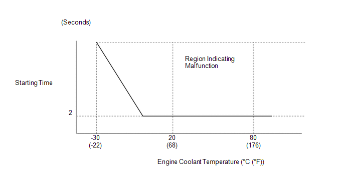
- The engine speed is below 500 rpm with the STA signal on for a certain amount of time (refer to the illustration below) (1 trip detection logic).
- After the engine starts (engine speed is 500 rpm or more), the engine speed drops to 200 rpm or less within approximately 2 seconds (1 trip detection logic).
| Last Modified: 08-28-2024 | 6.11:8.1.0 | Doc ID: RM100000000VIBV |
| Model Year Start: 2016 | Model: Sienna | Prod Date Range: [12/2015 - 08/2016] |
| Title: 2GR-FE (ENGINE CONTROL): SFI SYSTEM: P1604; Startability Malfunction; 2016 MY Sienna [12/2015 - 08/2016] | ||
|
DTC |
P1604 |
Startability Malfunction |
DESCRIPTION
This DTC is stored when the engine does not start even though the STA signal is input or when the engine takes a long time to start, and when the engine speed is low or the engine stalls just after the engine starts.
Using the Techstream, the conditions present when the DTC was stored can be confirmed by referring to the freeze frame data. Freeze frame data records engine conditions when a malfunction occurs. This information can be useful when troubleshooting.
It is necessary to check if the vehicle ran out of fuel before performing troubleshooting, as this DTC is also stored when there is engine starting trouble due to running out of fuel.
|
DTC No. |
DTC Detection Condition |
Trouble Area |
|---|---|---|
|
P1604 |
Either condition is met: |
|
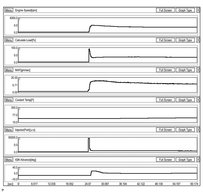
1. Reference waveforms showing a normal cold engine start
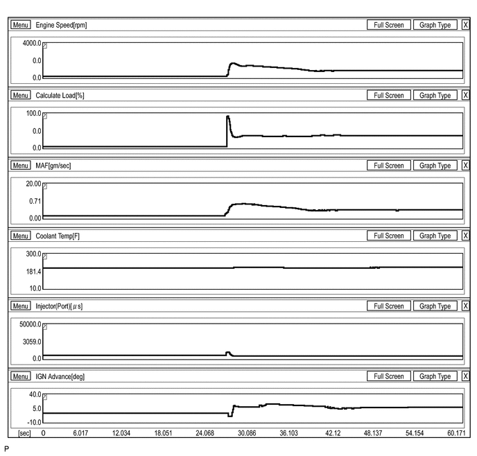
2. Reference waveforms showing a normal warm engine start
3. Reference values when there is an air leak in the intake system during starting difficulty
Freeze Frame Data P1604 Stability Malfunction
|
Parameter |
-3 |
-2 |
-1 |
0 |
1 |
Unit |
|---|---|---|---|---|---|---|
|
Engine Speed |
1625 |
1042 |
501 |
192 |
129 |
rpm |
|
Calculate Load |
43.1 |
30.5 |
38.8 |
93.3 |
93.3 |
% |
|
Vehicle Load |
9.0 |
16.0 |
28.2 |
34.1 |
29.8 |
% |
|
MAF |
6.01 |
6.67 |
5.64 |
2.62 |
1.54 |
gm/sec |
|
Atmosphere Pressure |
-1 |
-1 |
-1 |
-1 |
-1 |
psi(gauge) |
|
Coolant Temp |
180 |
180 |
180 |
180 |
180 |
F |
|
Intake Air |
122 |
120 |
118 |
118 |
118 |
F |
|
Battery Voltage |
12.460 |
12.519 |
12.187 |
12.128 |
12.050 |
V |
|
Throttle Sensor Volt % |
17.6 |
17.6 |
17.6 |
17.2 |
17.2 |
% |
|
Throttle Sensor #2 Volt % |
50.1 |
50.1 |
50.1 |
49.8 |
49.8 |
% |
|
Throttle Sensor Position |
0.0 |
0.0 |
0.0 |
0.0 |
0.0 |
% |
|
Throttle Motor DUTY |
17.6 |
17.6 |
17.6 |
17.2 |
17.2 |
% |
|
Injector (Port) |
3770 |
2465 |
2907 |
3245 |
7608 |
μs |
|
Injection Volum (Cylinder1) |
0.000 |
0.199 |
0.199 |
0.199 |
0.199 |
ml |
|
Fuel Pump/Speed Status |
ON |
ON |
ON |
ON |
ON |
|
|
EVAP (Purge) VSV |
0.0 |
0.0 |
0.0 |
0.0 |
0.0 |
% |
|
EVAP Purge Flow |
0.0 |
0.0 |
0.0 |
0.0 |
0.0 |
% |
|
Purge Density Learn Value |
0.000 |
0.000 |
0.000 |
0.000 |
0.000 |
|
|
EVAP Purge VSV |
OFF |
OFF |
OFF |
OFF |
OFF |
|
|
Purge Cut VSV Duty |
0.0 |
0.0 |
0.0 |
0.0 |
0.0 |
% |
|
Target Air-Fuel Ratio |
0.889 |
0.913 |
0.920 |
0.925 |
0.833 |
|
|
AF Lambda B1S1 |
0.998 |
0.998 |
0.998 |
0.998 |
0.998 |
|
|
AF Lambda B2S1 |
0.998 |
0.998 |
0.998 |
0.998 |
0.998 |
|
|
AFS Voltage B1S1 |
3.298 |
3.298 |
3.298 |
3.298 |
3.298 |
V |
|
AFS Voltage B2S1 |
3.298 |
3.298 |
3.298 |
3.298 |
3.298 |
V |
|
O2S B1S2 |
0.000 |
0.000 |
0.000 |
0.000 |
0.000 |
V |
|
O2S B2S2 |
0.000 |
0.000 |
0.000 |
0.000 |
0.000 |
V |
|
Short FT #1 |
0.000 |
0.000 |
0.000 |
0.000 |
0.000 |
% |
|
Long FT #1 |
0.000 |
0.000 |
0.000 |
-0.782 |
0.000 |
% |
|
Total FT #1 |
0.000 |
0.000 |
0.000 |
0.000 |
0.000 |
|
|
Short FT #2 |
0.000 |
0.000 |
0.000 |
0.000 |
0.000 |
% |
|
Long FT #2 |
1.562 |
0.781 |
0.781 |
0.781 |
0.781 |
% |
|
Total FT #2 |
0.000 |
0.000 |
0.000 |
0.000 |
0.000 |
|
|
Fuel System Status #1 |
OLFault |
OL |
OL |
OL |
OL |
|
|
Fuel System Status #2 |
OLFault |
OL |
OL |
OL |
OL |
|
|
IGN Advance |
0.0 |
17.5 |
13.5 |
0.0 |
0.0 |
deg |
|
Knock Feedback Value |
-3.0 |
-3.0 |
-3.0 |
-3.0 |
-3.0 |
deg(CA) |
|
Knock Correct Learn Value |
23.1 |
23.1 |
23.1 |
23.1 |
23.1 |
deg(CA) |
|
VVT Control Status #1 |
OFF |
OFF |
OFF |
OFF |
OFF |
|
|
VVT Control Status #2 |
OFF |
OFF |
OFF |
OFF |
OFF |
|
|
Starter Signal |
OFF |
OFF |
OFF |
OFF |
OFF |
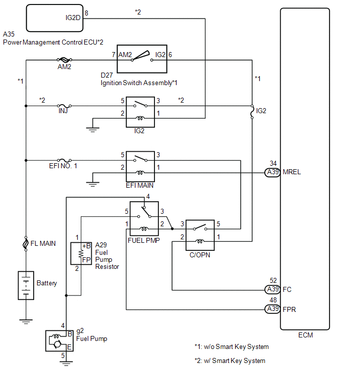
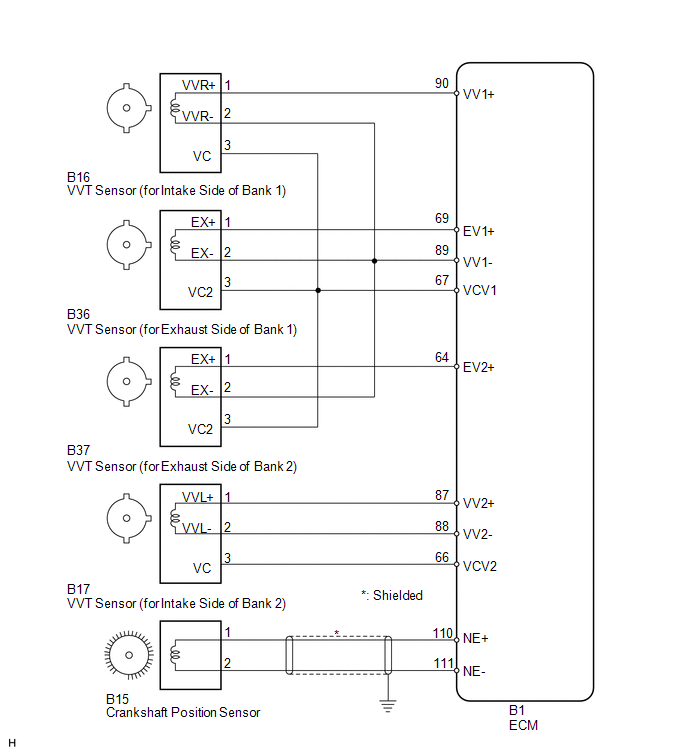
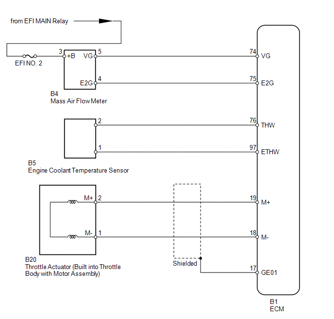
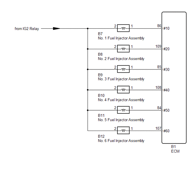
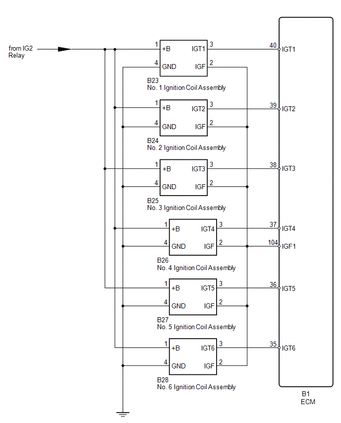
WIRING DIAGRAM
CAUTION / NOTICE / HINT
HINT:
-
In contrast to normal malfunction diagnosis for components, circuits and systems, DTC P1604 is used to determine the malfunctioning area from the problem symptoms and freeze frame data when the user mentions problems such as starting difficulty.
As these DTCs can be stored as a result of certain user actions, even if these DTCs are output, if the customer makes no mention of problems, clear these DTCs without performing any troubleshooting and return the vehicle to the customer.
- If any other DTCs are output, perform troubleshooting for those DTCs first.
- When the Data List item "Immobiliser Fuel Cut" is ON, the engine cannot be started.
- Read freeze frame data using the Techstream. Freeze frame data records engine conditions when a malfunction occurs. This information can be useful when troubleshooting.
-
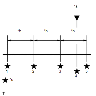
When confirming the freeze frame data, be sure to check all 5 sets of freeze frame data (See page
![2016 MY Sienna [12/2015 - 08/2016]; 2GR-FE (ENGINE CONTROL): SFI SYSTEM: FREEZE FRAME DATA](/t3Portal/stylegraphics/info.gif) ).
).
- When confirming freeze frame data, if there are multiple items related to the cause of the malfunction, perform troubleshooting for all related items.
- Try to start the vehicle under the conditions recorded in the freeze frame data which were present when the malfunction occurred. Confirm the data at this time and compare it with the freeze frame data.
- If the malfunction does not reoccur, carefully check the vehicle conditions from when the malfunction occurred using freeze frame data.
- When performing inspections, jiggle the relevant wire harnesses and connectors in an attempt to reproduce malfunctions that do not always occur.
- If the same inspection or replacement procedure appears 2 times when performing an inspection procedure, it is not necessary to repeat the procedure the second time.
1. Malfunction Recurrence and Inspection Areas
(a) Freeze frame data exists, but the malfunction (starting difficulty) has not reoccurred and the malfunction conditions are unknown.
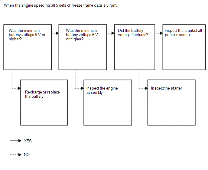
(1) The engine speed recorded in the freeze frame data is 0 rpm (the engine does not crank).
HINT:
One of the following problems may be present: battery depletion, excess engine friction, a starter malfunction or a crankshaft position sensor malfunction.
- If the battery voltage is less than 6 V during cranking, there is a high probability that engine friction is abnormal.
- If the battery voltage drops to 5 V or less when starting the engine, the battery may be malfunctioning.
-
If the battery voltage fluctuates while cranking the engine, it can be concluded that cranking is being performed. When the engine speed is 0 rpm, the crankshaft position sensor and/or an ECM may be malfunctioning.
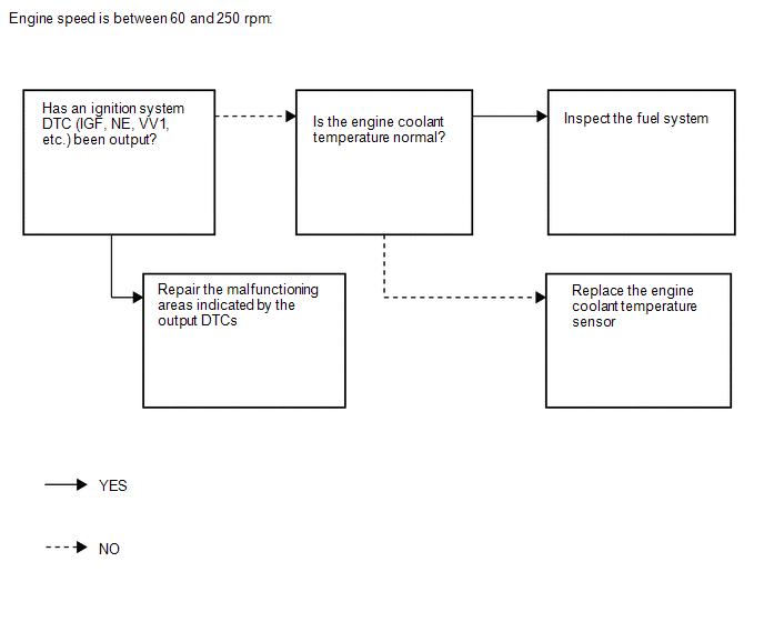
(2) All engine speeds recorded in the freeze frame data are between 60 and 250 rpm (the engine cranks but there is no combustion).
HINT:
If the engine speed is between 60 and 250 rpm (no initial combustion), there may be a wiring problem or a complete failure of an ignition or fuel system part.
-
Due to an engine coolant temperature sensor malfunction, the fuel injection volume is extremely high or low and the engine may not be able to be started.
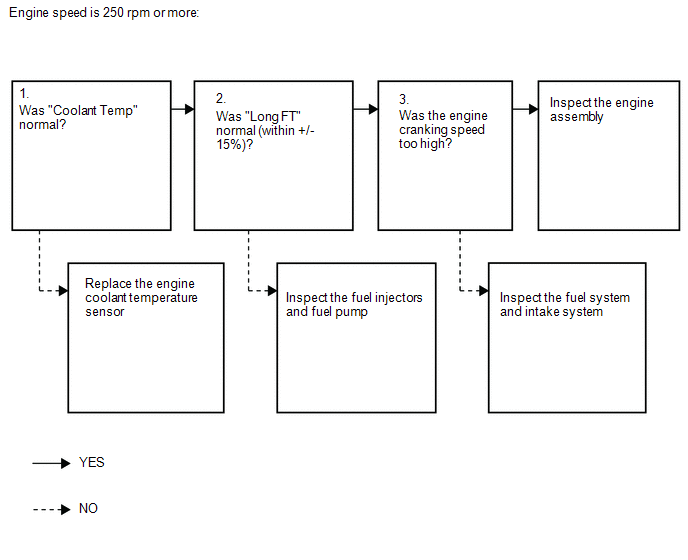
(3) The engine speed recorded in the freeze frame data is 250 rpm or higher (the initial combustion and starter turnoff timing is too late).
HINT:
If the engine speed is 250 rpm or higher (combustion occurs but the initial combustion and starter turnoff timing is too late), the fuel injection volume is often incorrect (too low or too high) and determining the cause of the malfunction is often difficult.
- Due to an engine coolant temperature sensor malfunction, the fuel injection volume is extremely high or low and engine starting trouble may occur.
- If Long FT #1 is incorrect, there may be a fuel supply problem due to the injectors or fuel pump being clogged, etc.
-
If the engine cranking speed is too high, compression loss may have occurred due to carbon interfering with the valve operation.
(b) When the malfunction (starting difficulty) can be reproduced, or malfunction conditions are known, perform the following inspections ("Problem symptoms" and "Systems to inspect")
(1) Problem symptoms
-
The engine does not crank.
HINT:
The starter is normal if a noise that indicates the starter pinion gear is extending is heard. The battery may be fully depleted or there may be excess engine friction.
-
The engine cranking speed is abnormal.
HINT:
If the engine cranking speed is too high (for example, 300 rpm or higher with no combustion), compression loss may have occurred because carbon interfered with valve operation, etc.
-
There is no initial combustion.
HINT:
If there is no initial combustion, there is probably a wiring problem or an ignition or fuel system part malfunction.
-
The engine stalls after starter turnoff.
HINT:
If the engine stalls after starter turnoff, the air fuel ratio may be incorrect or the VVT may have a problem returning.
-
The initial combustion and starter turnoff occur late.
HINT:
If the initial combustion and starter turnoff occur late, the fuel injection volume is probably incorrect (too low or too high).
HINT:
Causes of fuel system malfunctions according to conditions present at the time of the malfunction.
- When 2 to 3 minutes have elapsed after stopping the engine: Fuel pressure loss due to the pressure regulator failing to maintain the fuel pressure.
- When 15 to 120 minutes have elapsed after stopping the engine: Problem with injector fuel seal.
- When a long time has elapsed after stopping the engine: Pressure regulator is stuck open.
(2) Systems to inspect.
- Intake system
- Ignition system
- Fuel system
2. INSPECTION FLOW
(a) Freeze frame data exists, but the malfunction (starting difficulty) has not reoccurred and the malfunction conditions are unknown.
|
Freeze Frame Data Item |
Result |
Suspected Area |
Procedure |
|---|---|---|---|
|
Engine Speed |
0 rpm (no engine cranking at all) |
|
4 to 9 |
|
60 to 250 rpm (engine cranks but no initial combustion*1) |
|
10 to 14 |
|
|
250 rpm or higher (combustion occurs but initial combustion and starter turnoff*2 occur late) |
|
15 to 24 |
HINT:
- *1: First combustion after cranking begins.
- *2: Condition when engine speed increases and starter can be turned off.
(b) When the malfunction (starting difficulty) can be reproduced, or when malfunction conditions are known.
(1) Problem symptoms
|
Problem Symptom |
Suspected Area |
Suspected Component |
Procedure |
|---|---|---|---|
|
The engine does not crank |
Battery malfunction |
|
26 to 31 |
|
Starting system |
|
||
|
Engine assembly |
|
||
|
Cranking speed too low |
Battery malfunction |
|
32 to 34 |
|
Starting system |
|
||
|
Engine assembly |
|
||
|
Cranking speed too high |
Engine assembly |
|
|
|
There is no initial combustion |
Fuel supply problem |
|
35 to 50 |
|
Immobiliser system |
|
||
|
Ignition system malfunction |
|
||
|
Engine stalls after starter turnoff |
Air suction |
|
51 to 57 |
|
Deposits in throttle body |
|
||
|
VVT valve does not return properly |
|
||
|
Mass air flow meter malfunction |
|
||
|
The initial combustion and starter turnoff occur late |
Engine coolant temperature sensor malfunction |
|
58 to 71 |
|
Mass air flow meter malfunction |
|
||
|
Abnormal A/F learning value |
|
||
|
Deviation from fuel injection characteristics |
|
||
|
Wet-fouled or dry-fouled spark plug |
|
||
|
Lack of fuel pressure |
|
(2) Systems to inspect.
|
Troubleshooting by System |
Suspected Area |
Suspected Component |
Procedure |
|---|---|---|---|
|
Fuel system troubleshooting A |
Abnormal A/F learning value |
|
88 to 95 96 to 103 |
|
Rough idling |
|
||
|
Abnormal fuel pressure |
|
||
|
Fuel system troubleshooting B |
Abnormal concentration of HC in surge tank |
|
104 to 106 |
|
Fuel system troubleshooting C |
Injection signal system malfunction |
|
73 to 77 |
|
Intake system troubleshooting |
Difference between ISC target value and opening angle when idling |
|
85 to 87 107 to 109 |
|
Ignition system troubleshooting |
VVT sensor and/or crankshaft position sensor signal malfunction |
|
78 to 84 110 to 116 |
NOTICE:
- Inspect the fuses for circuits related to this system before performing the following inspection procedure.
-
After turning ignition switch off, waiting time may be required before disconnecting the cable from the negative (-) battery terminal. Therefore, make sure to read the disconnecting the cable from the negative (-) battery terminal notices before proceeding with work (See page
).
HINT:
- Read freeze frame data using the Techstream. The ECM records vehicle and driving condition information as freeze frame data the moment a DTC is stored. When troubleshooting, freeze frame data can help determine if the vehicle was moving or stationary, if the engine was warmed up or not, if the air fuel ratio was lean or rich, and other data from the time the malfunction occurred.
- Bank 1 refers to the bank that includes the No. 1 cylinder.
- Bank 2 refers to the bank that does not include the No. 1 cylinder.
PROCEDURE
|
1. |
CHECK ANY OTHER DTCS OUTPUT AND RECORD FREEZE FRAME DATA |
(a) Connect the Techstream to the DLC3.
(b) Turn the ignition switch to ON.
(c) Enter the following menus: Powertrain / Engine / Trouble Codes.
|
(d) Read the DTCs and record the Freeze Frame Data. HINT:
Text in Illustration
Result
|
|
| B |

|
|

|
2. |
CHECK ENGINE IMMOBILISER SYSTEM |
(a) Connect the Techstream to the DLC3.
(b) Turn the ignition switch to ON.
(c) Turn the Techstream on.
(d) Enter the following menus: Powertrain / Engine / Data List / Immobiliser Fuel Cut.
(e) Read the value displayed on the Techstream.
OK:
Immobiliser Fuel Cut is OFF
Result
|
Result |
Proceed to |
|---|---|
|
OK |
A |
|
NG (w/o Smart Key System) |
B |
|
NG (w/ Smart Key System) |
C |
HINT:
- If the engine is started immediately after reconnecting the battery terminal, the engine may stall immediately after it starts due to the intercommunication process between each ECU. For this reason, when starting the engine after reconnecting the battery terminal, first turn the ignition switch to ON and then wait several seconds for the communication process to complete before starting the engine.
- When this operation causes DTC P1604 to be stored, this is due to normal operation of the immobiliser system and does not indicate a malfunction, so clear the DTC and return the vehicle to the customer.
| B |
|
| C |
|
|
|
3. |
CHECK MALFUNCTION CONDITION |
(a) Confirm the problem symptoms.
Result
|
Result |
Proceed to |
|---|---|
|
Freeze frame data exists, but the starting difficulty cannot be reproduced and it is unknown what kind of starting difficulty occurred |
A |
|
The problem symptoms can be reproduced, or the malfunction conditions are known |
B |
| B |
|
|
|
4. |
READ FREEZE FRAME DATA |
(a) Connect the Techstream to the DLC3.
(b) Turn the ignition switch to ON.
(c) Using the Techstream, confirm the vehicle conditions recorded in the freeze frame data which were present when the DTC was stored (See page
).
Result
|
Freeze Frame Data Item |
Suspected Area |
Proceed to |
|
|---|---|---|---|
|
Engine Speed |
Battery Voltage |
||
|
All 5 sets of freeze frame data are 0 rpm (no engine cranking at all) |
Minimum voltage is less than 5 V |
Battery fully depleted |
A |
|
Minimum voltage is 5 V or higher |
|
B |
|
|
60 to 250 rpm (engine cranks but no initial combustion) |
- |
|
C |
|
250 rpm or higher (combustion occurs but initial combustion and starter turnoff occur late) |
- |
|
D |
Result
|
Freeze Frame Data Item |
Suspected Area |
Proceed to |
|---|---|---|
|
Low Rev for Eng Start |
||
|
ON exists |
|
E |
HINT:
When DTC P1604 is stored, either "Engine Start Hesitation"*1 or "Low Rev for Eng Start"*2 in the Freeze Frame Data will be ON. If "Low Rev for Eng Start" is ON, proceed to E.
*1: This value turns ON when the engine speed does not reach a certain value for a certain period of time when starting the engine.
*2: This value turns ON when the engine stalls immediately after starting the engine. If "Low Rev for Eng Start" is ON, as there is a possibility that the low engine speed or engine stall was caused by the user, confirm the following freeze frame data items.
- Immobiliser Fuel Cut
- Engine Speed (Starter Off)
- Shift SW Status (R, D Range)
| A |
|
CHARGE OR REPLACE BATTERY |
| C |
|
| D |
|
| E |
|
|
|
5. |
READ FREEZE FRAME DATA |
(a) Connect the Techstream to the DLC3.
(b) Turn the ignition switch to ON.
(c) Using the Techstream, confirm the vehicle conditions recorded in the freeze frame data which were present when the DTC was stored (See page
).
Result
|
Freeze Frame Data Item |
Result |
Suspected Area |
Proceed to |
|---|---|---|---|
|
Battery Voltage |
Minimum voltage is 6 V or higher and voltage does not fluctuate*1 |
Starter system |
A*5 B*6 |
|
Minimum voltage is 6 V or higher and voltage fluctuates*2, *3 |
|
C |
|
|
Minimum voltage is 5 to 6 V*4 |
|
D |
HINT:
-
*1: The 5 sets of freeze frame data show approximately the same battery voltage.
- *2: The 5 sets of freeze frame data show different battery voltages.
- *3: If the voltage fluctuates, it can be determined that cranking is being performed. When the engine speed is 0 rpm, the crankshaft position sensor system and/or the ECM may be malfunctioning.
- *4: There may be excess engine friction. Make sure that the crankshaft rotates smoothly when turning it by hand. Excess engine friction may have occurred temporarily. Remove the cylinder head cover and oil pan, and check for foreign matter such as iron fragments. If there is a malfunction or signs of a malfunction present, perform a detailed inspection by disassembling all the parts.
- *5: w/o Smart key system
-
*6: w/ Smart key system
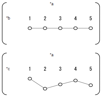
Text in Illustration
*a
Freeze Frame Data
*b
Voltage does not Fluctuate
*c
Voltage Fluctuates
| A |
|
| B |
|
CHECK CRANKING HOLDING FUNCTION CIRCUIT (W/ SMART KEY SYSTEM) |
| D |
|
CHECK AND REPAIR ENGINE OR BATTERY |
|
|
6. |
CHECK CRANKSHAFT POSITION SENSOR INSTALLATION |
(a) Check the tightening and installation condition of the crankshaft position sensor bolt.
(b) Check the connection of the crankshaft position sensor connector.
| NG |
|
|
|
7. |
CHECK CRANKSHAFT POSITION SENSOR |
(a) Disconnect the B15 crankshaft position sensor connector.
(b) Check for oil on the connector terminals.
OK:
No oil on the terminals.
| NG |
|
|
|
8. |
CHECK HARNESS AND CONNECTOR (CRANKSHAFT POSITION SENSOR - ECM) |
(a) Disconnect the B15 crankshaft position sensor connector.
(b) Disconnect the B1 ECM connector.
(c) Measure the resistance according to the value(s) in the table below.
Standard Resistance:
|
Tester Connection |
Condition |
Specified Condition |
|---|---|---|
|
B15-1 - B1-110 (NE+) |
Always |
Below 1 Ω |
|
B15-2 - B1-111 (NE-) |
Always |
Below 1 Ω |
|
B15-1 or B1-110 (NE+) - Body ground |
Always |
10 kΩ or higher |
|
B15-2 or B1-111 (NE-) - Body ground |
Always |
10 kΩ or higher |
HINT:
- Jiggle the wire harness and connector to increase the likelihood of detecting malfunctions that do not always occur.
- Make sure there is not an excessive amount of force applied to the wire harness.
| NG |
|
REPAIR OR REPLACE HARNESS OR CONNECTOR |
|
|
9. |
INSPECT CRANKSHAFT POSITION SENSOR |
(a) Replace the crankshaft position sensor (See page
).
(b) Check the engine start operation.
OK:
Malfunction has been repaired successfully.
| OK |
|
END (CRANKSHAFT POSITION SENSOR IS DEFECTIVE) |
| NG |
|
|
10. |
READ FREEZE FRAME DATA |
(a) Connect the Techstream to the DLC3.
(b) Turn the ignition switch to ON.
(c) Using the Techstream, confirm the vehicle conditions recorded in the freeze frame data which were present when the DTC was stored (See page
).
Result
|
Freeze Frame Data Item |
Suspected Area |
Proceed to |
||
|---|---|---|---|---|
|
Coolant Temp, Ambient Temperature, Intake Air |
Coolant Temp, Ambient Temperature |
Fuel Pump/Speed Status |
||
|
Difference between Coolant Temp, Ambient Temperature and Intake Air is 10°C (18°F) or more*1 |
Coolant Temp is 125°C (257°F) or more, or lower than Ambient Temperature by 15°C (27°F) or more |
- |
Engine coolant temperature sensor |
A |
|
Other than above |
All 5 sets of freeze frame data are ON |
- |
B |
|
|
At least 1 of the 5 sets of freeze frame data is OFF |
Fuel pump control system |
C |
||
|
Difference between Coolant Temp, Ambient Temperature and Intake Air is less than 10°C (18°F)*2 |
- |
At least 1 of the 5 sets of freeze frame data is OFF |
Fuel pump control system |
C |
|
All 5 sets of freeze frame data are ON |
- |
B |
||
HINT:
- *1: A long time had not elapsed after stopping the engine.
- *2: A long time had elapsed after stopping the engine.
| A |
|
| C |
|
|
|
11. |
PERFORM ACTIVE TEST USING TECHSTREAM (CONTROL THE FUEL PUMP/SPEED) |
(a) Connect the Techstream to the DLC3.
(b) Disconnect the fuel pump connector.
(c) Turn the ignition switch to ON.
(d) Turn the Techstream on.
(e) Enter the following menus: Powertrain / Engine / Active Test / Control the Fuel Pump/Speed.
(f) Measure the voltage according to the value(s) in the table below.
Standard Voltage:
|
Tester Connection |
Condition |
Specified Condition |
|---|---|---|
|
g2-4 (B) - Body ground |
Active Test is being performed |
11 to 14 V |
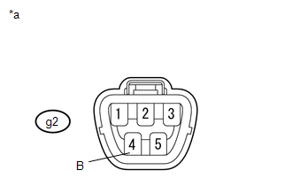
Text in Illustration
|
*a |
Front view of wire harness connector (to Fuel Pump Connector) |
HINT:
- Jiggle the wire harness and connector to increase the likelihood of detecting malfunctions that do not always occur.
- Make sure there is not an excessive amount of force applied to the wire harness.
| NG |
|
|
|
12. |
CHECK TERMINAL VOLTAGE (FUEL INJECTOR ASSEMBLY POWER SOURCE) |
|
(a) Disconnect the fuel injector assembly connectors. |
|
(b) Turn the ignition switch to ON.
(c) Measure the voltage according to the value(s) in the table below.
Standard Voltage:
|
Tester Connection |
Switch Condition |
Specified Condition |
|---|---|---|
|
B7-2 - Body ground |
Ignition switch ON |
11 to 14 V |
|
B8-2 - Body ground |
Ignition switch ON |
11 to 14 V |
|
B9-2 - Body ground |
Ignition switch ON |
11 to 14 V |
|
B10-2 - Body ground |
Ignition switch ON |
11 to 14 V |
|
B11-2 - Body ground |
Ignition switch ON |
11 to 14 V |
|
B12-2 - Body ground |
Ignition switch ON |
11 to 14 V |
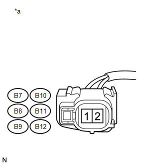
Text in Illustration
|
*a |
Front view of wire harness connector (to Fuel Injector Assembly) |
HINT:
- Jiggle the wire harness and connector to increase the likelihood of detecting malfunctions that do not always occur.
- Make sure there is not an excessive amount of force applied to the wire harness.
- A rapid decrease in engine speed may have been caused by a malfunction in all or multiple cylinders. (There may be an electrical malfunction in the wiring shared by all the cylinders.)
| NG |
|
|
|
13. |
PERFORM ACTIVE TEST USING TECHSTREAM (CONTROL THE FUEL PUMP/SPEED) |
(a) Connect the Techstream to the DLC3.
(b) Turn the ignition switch to ON.
(c) Turn the Techstream on.
(d) Enter the following menus: Powertrain / Engine / Active Test / Control the Fuel Pump/Speed.
(e) When performing the Active Test, check for fuel leakage from the fuel pipes.
Result
|
Result |
Proceed to |
|---|---|
|
Fuel leakage or signs of fuel leakage are present |
A |
|
No fuel leakage or signs of fuel leakage |
B |
HINT:
- Jiggle the wire harness and connector to increase the likelihood of detecting malfunctions that do not always occur.
- When performing the Active Test, if there is no operating noise from the fuel pump, the fuel pump system may be malfunctioning.
- Check if the vehicle ran out of fuel, as engine starting trouble due to running out of fuel is also detected.
| A |
|
REPAIR OR REPLACE FUEL LINE |
|
|
14. |
CHECK FUEL SYSTEM |
(a) Check for foreign matter such as iron particles around the fuel pump (fuel pump, fuel pump filter, and inside the fuel tank), and for signs that the fuel pump was stuck.
Result
|
Result |
Proceed to |
|---|---|
|
There is foreign matter or signs that fuel pump was stuck |
A |
|
There is no foreign matter and no signs that fuel pump was stuck |
B |
| A |
|
REPAIR OR REPLACE FUEL SYSTEM |
| B |
|
|
15. |
READ FREEZE FRAME DATA |
(a) Connect the Techstream to the DLC3.
(b) Turn the ignition switch to ON.
(c) Using the Techstream, confirm the vehicle conditions recorded in the freeze frame data which were present when the DTC was stored (See page
).
Result
|
Freeze Frame Data Item |
Suspected Area |
Proceed to |
|||
|---|---|---|---|---|---|
|
Coolant Temp, Ambient Temperature, Intake Air |
Coolant Temp, Ambient Temperature |
Long FT #1 |
Engine Speed |
||
|
Difference between Coolant Temp, Ambient Temperature and Intake Air is 10°C (18°F) or more |
Coolant Temp is 125°C (257°F) or more, or lower than Ambient Temperature by 15°C (27°F) or more |
- |
- |
Engine coolant temperature sensor |
A |
|
Other than above |
-15% or less, or +15% or more |
- |
|
B |
|
|
-15 to +15% |
Minimum speed is 300 rpm or more*1 |
Engine assembly |
C |
||
|
Minimum speed is below 300 rpm |
|
D |
|||
|
Difference between Coolant Temp, Ambient Temperature and Intake Air is less than 10°C (18°F) |
- |
-15% or less, or +15% or more |
- |
|
B |
|
-15 to +15% |
Minimum speed is 300 rpm or more*1 |
Engine assembly |
C |
||
|
Minimum speed is below 300 rpm |
|
D |
|||
HINT:
*1: Compression loss may have occurred in the engine assembly.
| A |
|
| C |
|
CHECK AND REPAIR ENGINE ASSEMBLY |
| D |
|
|
|
16. |
INSPECT FUEL INJECTOR ASSEMBLY |
(a) Check that no carbon is stuck to the fuel injector assembly.
OK:
No carbon present.
HINT:
Perform "Inspection After Repair" after replacing the fuel injector assembly (See page
).
| NG |
|
|
|
17. |
CHECK FUEL SYSTEM |
(a) Check for foreign matter such as iron particles around the fuel pump (fuel pump, fuel pump filter, and inside the fuel tank), and for signs that the fuel pump was stuck.
Result
|
Result |
Proceed to |
|---|---|
|
There is foreign matter or signs that fuel pump was stuck |
A |
|
There is no foreign matter and no signs that fuel pump was stuck |
B |
| A |
|
REPAIR OR REPLACE FUEL SYSTEM |
| B |
|
|
18. |
READ FREEZE FRAME DATA |
(a) Connect the Techstream to the DLC3.
(b) Turn the ignition switch to ON.
(c) Using the Techstream, confirm the vehicle conditions recorded in the freeze frame data which were present when the DTC was stored (See page
).
Result
|
Freeze Frame Data Item |
Result |
Suspected Area |
Proceed to |
|---|---|---|---|
|
Coolant Temp |
Engine coolant temperature is 40°C (104°F) or less*1 |
Pressure regulator |
A |
|
Engine coolant temperature is 40 to 90°C (104 to 194°F)*2 |
Fuel injector assembly |
B |
|
|
Engine coolant temperature is 90°C (194°F) or more*3 |
Pressure regulator |
A |
HINT:
*1: If the engine coolant temperature is 40°C (104°F) or less (after stopping the engine and the vehicle is not driven for a long period of time), the pressure regulator may be stuck open. Attach a fuel pressure gauge and check the ability to maintain fuel pressure after stopping the engine.
*2: If the engine coolant temperature is 40 to 90°C (104 to 194°F) (15 to 120 minutes have passed after stopping the engine), there may be fuel leaking from a fuel injector assembly.
*3: If the engine coolant temperature is 90°C (194°F) or more (2 to 5 minutes have passed after stopping the engine), there may be a problem with the pressure regulator failing to maintain the fuel pressure. Attach a fuel pressure gauge and check the ability to maintain fuel pressure after stopping the engine.
| B |
|
|
|
19. |
CHECK FUEL PRESSURE |
HINT:
For the fuel pressure inspection, refer to the following procedures (See page
).
(a) Attach a fuel pressure gauge and check the fuel pressure after stopping the engine.
Standard:
147 kPa (1.5 kgf/cm2) or higher (5 minutes after stopping the engine)
HINT:
If the engine cannot be started, read the values after cranking the engine.
Result
|
Result |
Proceed to |
|---|---|
|
NG |
A |
|
OK |
B |
| A |
|
| B |
|
|
20. |
CHECK FUEL INJECTOR ASSEMBLY |
(a) Clean the inside of the surge tank with compressed air.
(b) After stopping the engine, measure the HC concentration inside the surge tank for 15 minutes.
Result
|
Result |
Proceed to |
|---|---|
|
4000 ppm or higher |
A |
|
Less than 4000 ppm |
B |
HINT:
If the concentration is 4000 ppm or higher, a fuel injector assembly may have a sealing problem.
| B |
|
|
|
21. |
INSPECT FUEL INJECTOR ASSEMBLY |
(a) Inspect the fuel injector assembly (See page
).
HINT:
Perform "Inspection After Repair" after replacing the fuel injector assembly (See page
).
| NG |
|
|
|
22. |
CHECK THROTTLE BODY WITH MOTOR ASSEMBLY |
(a) Check if carbon is in the air flow passage.
Result
|
Result |
Proceed to |
|---|---|
|
Carbon in passage |
A |
|
No carbon present |
B |
HINT:
Perform "Inspection After Repair" after cleaning or repairing the throttle body with motor assembly (See page
).
| A |
|
|
|
23. |
CHECK INTAKE SYSTEM |
(a) Check the intake system for vacuum leak (See page
).
OK:
No leak in intake system.
HINT:
Perform "Inspection After Repair" after repairing or replacing the intake system (See page
).
| NG |
|
REPAIR OR REPLACE INTAKE SYSTEM |
|
|
24. |
PERFORM SIMULATION TEST |
(a) Check if the engine can be started.
Result
|
Result |
Proceed to |
|---|---|
|
Engine can be started |
A |
|
Engine cannot be started |
B |
| A |
|
END |
|
|
25. |
CONFIRM PROBLEM SYMPTOM |
(a) Confirm the problem symptoms.
HINT:
The problem symptoms below can be determined by reading the freeze frame data.
Result
|
Problem Symptom |
Suspected Area |
Proceed to |
|---|---|---|
|
The engine does not crank |
|
A |
|
Abnormal cranking speed |
|
B |
|
There is no initial combustion (combustion does not occur even once)*1 |
|
C |
|
The engine stalls after starter turnoff (engine stalls immediately after the first time the engine speed increases)*2 |
|
D |
|
The initial combustion and starter turnoff occur late*3 |
|
E |
HINT:
- If there is hesitation (cranking speed is slow and combustion occurs before passing TDC) during the initial cranking period, the battery charge may be insufficient or the starter may be malfunctioning.
- *1: If there is no initial combustion, a wire harness may be malfunctioning, or the ignition or fuel system may be malfunctioning.
- *2: If the engine stalls after starter turnoff, the air fuel ratio may be incorrect or the camshaft timing oil control valve may have a problem returning.
- *3: If the initial combustion and starter turnoff occur late, the fuel injection volume may be incorrect (too low or too high).
| B |
|
| C |
|
| D |
|
| E |
|
|
|
26. |
PERFORM SIMULATION TEST |
(a) When cranking the engine, check for a noise indicating that the starter pinion gear is extending, and check that the starter pinion gear is not spinning freely.
Result
|
Problem Symptom |
Suspected Area |
Proceed to |
|---|---|---|
|
A noise indicating that the starter pinion gear is extending is heard and the starter pinion gear is not spinning freely.*1 |
|
A |
|
A noise indicating that the starter pinion gear is extending is heard but the starter pinion gear is spinning freely. |
|
B |
|
A noise indicating that the starter pinion gear is extending is not heard |
|
C |
HINT:
*1: The battery may be fully depleted or there may be excess engine friction.
| B |
|
| C |
|
|
|
27. |
INSPECT BATTERY |
(a) Inspect the battery (See page
).
| NG |
|
CHARGE OR REPLACE BATTERY |
|
|
28. |
CHECK ENGINE ASSEMBLY |
(a) Check that the crankshaft rotates smoothly when rotating it by hand.
OK:
Crankshaft rotates smoothly.
HINT:
- Excess engine friction may have occurred temporarily. Remove the cylinder head cover and oil pan, and check for foreign matter such as iron fragments. If there is a malfunction or signs of a malfunction present, perform a detailed inspection by disassembling all the parts.
-
Perform "Inspection After Repair" after repairing or replacing the engine assembly (See page
).
| OK |
|
| NG |
|
REPAIR OR REPLACE ENGINE ASSEMBLY |
|
29. |
CHECK STARTER ASSEMBLY |
(a) Remove the starter assembly (See page
).
(b) Check for starter pinion gear wear and damage.
Standard:
There is no wear or damage.
| OK |
|
| NG |
|
|
30. |
INSPECT BATTERY |
(a) Inspect the battery (See page
).
| NG |
|
CHARGE OR REPLACE BATTERY |
|
|
31. |
INSPECT STARTER ASSEMBLY |
(a) Inspect the starter assembly (See page
).
Result
|
Result |
Proceed to |
|---|---|
|
NG |
A |
|
OK (w/o Smart Key System) |
B |
|
OK (w/ Smart Key System) |
C |
| A |
|
| B |
|
| C |
|
CHECK CRANKING HOLDING FUNCTION CIRCUIT (W/ SMART KEY SYSTEM) |
|
32. |
PERFORM SIMULATION TEST |
(a) Check the cranking speed.
Result
|
Problem Symptom |
Suspected Area |
Proceed to |
|---|---|---|
|
Cranking speed is slow (100 rpm or less) |
|
A |
|
Cranking speed is fast (300 rpm or more)*1 |
Engine compression loss |
B |
HINT:
*1: If the cranking speed is fast, there may be compression loss.
| B |
|
CHECK AND REPAIR ENGINE ASSEMBLY |
|
|
33. |
INSPECT BATTERY |
(a) Inspect the battery (See page
).
| NG |
|
CHARGE OR REPLACE BATTERY |
|
|
34. |
CHECK ENGINE ASSEMBLY |
(a) Check that the crankshaft rotates smoothly when rotating it by hand.
OK:
Crankshaft rotates smoothly.
HINT:
- Excess engine friction may have occurred temporarily. Remove the cylinder head cover and oil pan, and check for foreign matter such as iron fragments. If there is a malfunction or signs of a malfunction present, perform a detailed inspection by disassembling all the parts.
-
Perform "Inspection After Repair" after repairing or replacing the engine assembly (See page
).
| OK |
|
| NG |
|
REPAIR OR REPLACE ENGINE ASSEMBLY |
|
35. |
CHECK FUEL INJECTOR ASSEMBLY |
(a) Using a sound scope or screwdriver, check for an injector operating noise while cranking the engine.
OK:
Fuel injector assembly operating noise is heard.
| NG |
|
|
|
36. |
CHECK FUEL PRESSURE |
(a) Check the fuel pressure (See page
).
| NG |
|
|
|
37. |
INSPECT SPARK PLUG AND SPARK |
(a) Inspect for sparks (See page
).
| NG |
|
|
|
38. |
CONFIRM VEHICLE CONDITION |
(a) Confirm the conditions present when the malfunction occurred based on the customer problem analysis.
Result
|
Problem Symptom |
Suspected Area |
Proceed to |
|---|---|---|
|
When the engine is stopped and a long time has passed, engine starting trouble occurs*1 |
Pressure regulator is stuck open |
A |
|
When the engine is stopped and approximately 15 to 120 minutes have passed, engine starting trouble occurs*2 |
Fuel injector assembly leak |
B |
|
When the engine is stopped and approximately 2 to 3 minutes have passed, engine starting trouble occurs*3 |
Failure to maintain fuel pressure by pressure regulator |
A |
|
Condition other than above, or there is an inconsistency in the conditions present when engine starting trouble occurs |
- |
C*4 |
HINT:
*1: The pressure regulator may be stuck open. Attach a fuel pressure gauge and check the ability to maintain fuel pressure after stopping the engine.
*2: Fuel may be leaking from a fuel injector assembly.
*3: The pressure regulator may not be able to maintain the fuel pressure. Attach a fuel pressure gauge and check the ability to maintain fuel pressure after stopping the engine.
*4: From step 72, perform fuel system troubleshooting C (steps 73 to 77).
| B |
|
| C |
|
|
|
39. |
CHECK FUEL PRESSURE |
HINT:
For the fuel pressure inspection, refer to the following procedures (See page
).
(a) Attach a fuel pressure gauge and check the fuel pressure after stopping the engine.
Result
|
Result |
Proceed to |
|---|---|
|
Less than 147 kPa (1.5 kgf/cm2) (5 minutes after stopping the engine) |
A |
|
147 kPa (1.5 kgf/cm2) or higher (5 minutes after stopping the engine) |
B*1 |
HINT:
- If the engine cannot be started, check the fuel pressure after cranking the engine.
- *1: From step 72, perform fuel system troubleshooting C (steps 73 to 77).
| A |
|
| B |
|
|
40. |
CHECK FUEL INJECTOR ASSEMBLY |
(a) After stopping the engine, measure the HC concentration inside the surge tank for 15 minutes.
Result
|
Result |
Proceed to |
|---|---|
|
4000 ppm or higher |
A |
|
Less than 4000 ppm |
B*1 |
HINT:
- If the concentration is 4000 ppm or higher, a fuel injector assembly may have a sealing problem.
- *1: From step 72, perform fuel system troubleshooting C (steps 73 to 77).
-
Perform "Inspection After Repair" after replacing the fuel injector assembly (See page
).
| A |
|
| B |
|
|
41. |
INSPECT SPARK PLUG |
(a) Inspect the spark plugs (See page
).
HINT:
- Even if the spark plug of only one cylinder is malfunctioning, replace the spark plugs of all cylinders.
-
Perform "Inspection After Repair" after replacing the spark plug (See page
).
| NG |
|
|
|
42. |
READ VALUE USING TECHSTREAM (ENGINE SPEED) |
(a) Connect the Techstream to the DLC3.
(b) Turn the ignition switch to ON.
(c) Turn the Techstream on.
(d) Enter the following menus: Powertrain / Engine / Data List / Engine Speed.
(e) Start the engine.
(f) While running the engine, read the [Engine Speed] value.
OK:
A value that matches the actual engine speed is constantly output.
HINT:
- Check the engine speed using a line graph.
- If the engine cannot be started, check the engine speed while cranking the engine.
- If the engine speed is 0 rpm, the crankshaft position sensor may have an open or short circuit.
| NG |
|
|
|
43. |
CHECK TERMINAL VOLTAGE (IGNITION COIL ASSEMBLY POWER SOURCE) |
|
(a) Disconnect the ignition coil assembly connectors. |
|
(b) Turn the ignition switch to ON.
(c) Measure the voltage according to the value(s) in the table below.
Standard Voltage:
|
Tester Connection |
Switch Condition |
Specified Condition |
|---|---|---|
|
B23-1 (+B) - B23-4 (GND) |
Ignition switch ON |
11 to 14 V |
|
B24-1 (+B) - B24-4 (GND) |
Ignition switch ON |
11 to 14 V |
|
B25-1 (+B) - B25-4 (GND) |
Ignition switch ON |
11 to 14 V |
|
B26-1 (+B) - B26-4 (GND) |
Ignition switch ON |
11 to 14 V |
|
B27-1 (+B) - B27-4 (GND) |
Ignition switch ON |
11 to 14 V |
|
B28-1 (+B) - B28-4 (GND) |
Ignition switch ON |
11 to 14 V |
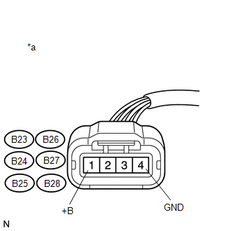
Text in Illustration
|
*a |
Front view of wire harness connector (to Ignition Coil Assembly) |
HINT:
- Jiggle the wire harness and connector to increase the likelihood of detecting malfunctions that do not always occur.
- Make sure there is not an excessive amount of force applied to the wire harness.
- A rapid decrease in engine speed may have been caused by a malfunction in all or multiple cylinders. (There may be an electrical malfunction in the wiring shared by all the cylinders.)
| NG |
|
|
|
44. |
CHECK HARNESS AND CONNECTOR (IGNITION COIL ASSEMBLY - ECM) |
(a) Disconnect the B23, B24, B25, B26, B27 and B28 ignition coil assembly connectors.
(b) Disconnect the B1 ECM connector.
(c) Measure the resistance according to the value(s) in the table below.
Standard Resistance:
|
Tester Connection |
Condition |
Specified Condition |
|---|---|---|
|
B23-2 (IGF) - B1-104 (IGF1) |
Always |
Below 1 Ω |
|
B24-2 (IGF) - B1-104 (IGF1) |
Always |
Below 1 Ω |
|
B25-2 (IGF) - B1-104 (IGF1) |
Always |
Below 1 Ω |
|
B26-2 (IGF) - B1-104 (IGF1) |
Always |
Below 1 Ω |
|
B27-2 (IGF) - B1-104 (IGF1) |
Always |
Below 1 Ω |
|
B28-2 (IGF) - B1-104 (IGF1) |
Always |
Below 1 Ω |
|
B23-2 (IGF) or B1-104 (IGF1) - Body ground |
Always |
10 kΩ or higher |
|
B24-2 (IGF) or B1-104 (IGF1) - Body ground |
Always |
10 kΩ or higher |
|
B25-2 (IGF) or B1-104 (IGF1) - Body ground |
Always |
10 kΩ or higher |
|
B26-2 (IGF) or B1-104 (IGF1) - Body ground |
Always |
10 kΩ or higher |
|
B27-2 (IGF) or B1-104 (IGF1) - Body ground |
Always |
10 kΩ or higher |
|
B28-2 (IGF) or B1-104 (IGF1) - Body ground |
Always |
10 kΩ or higher |
HINT:
- Jiggle the wire harness and connector to increase the likelihood of detecting malfunctions that do not always occur.
- Make sure there is not an excessive amount of force applied to the wire harness.
-
Perform "Inspection After Repair" after replacing the ignition coil assembly (See page
).
| NG |
|
REPAIR OR REPLACE HARNESS OR CONNECTOR |
|
|
45. |
CHECK HARNESS AND CONNECTOR (IGNITION COIL ASSEMBLY - ECM) |
(a) Disconnect the B23, B24, B25, B26, B27 and B28 ignition coil assembly connectors.
(b) Disconnect the B1 ECM connector.
(c) Measure the resistance according to the value(s) in the table below.
Standard Resistance:
|
Tester Connection |
Condition |
Specified Condition |
|---|---|---|
|
B23-3 (IGT1) - B1-40 (IGT1) |
Always |
Below 1 Ω |
|
B24-3 (IGT2) - B1-39 (IGT2) |
Always |
Below 1 Ω |
|
B25-3 (IGT3) - B1-38 (IGT3) |
Always |
Below 1 Ω |
|
B26-3 (IGT4) - B1-37 (IGT4) |
Always |
Below 1 Ω |
|
B27-3 (IGT5) - B1-36 (IGT5) |
Always |
Below 1 Ω |
|
B28-3 (IGT6) - B1-35 (IGT6) |
Always |
Below 1 Ω |
|
B23-3 (IGT1) or B1-40 (IGT1) - Body ground |
Always |
10 kΩ or higher |
|
B24-3 (IGT2) or B1-39 (IGT2) - Body ground |
Always |
10 kΩ or higher |
|
B25-3 (IGT3) or B1-38 (IGT3) - Body ground |
Always |
10 kΩ or higher |
|
B26-3 (IGT4) or B1-37 (IGT4) - Body ground |
Always |
10 kΩ or higher |
|
B27-3 (IGT5) or B1-36 (IGT5) - Body ground |
Always |
10 kΩ or higher |
|
B28-3 (IGT6) or B1-35 (IGT6) - Body ground |
Always |
10 kΩ or higher |
HINT:
- Jiggle the wire harness and connector to increase the likelihood of detecting malfunctions that do not always occur.
- Make sure there is not an excessive amount of force applied to the wire harness.
- If the wire harness is normal, after replacing the ignition coil assembly, check if engine starting trouble occurs again. If engine starting trouble occurs again, proceed to step 72 and perform troubleshooting for the ignition system (steps 78 to 84).
| OK |
|
| NG |
|
REPAIR OR REPLACE HARNESS OR CONNECTOR |
|
46. |
PERFORM ACTIVE TEST USING TECHSTREAM (CONTROL THE FUEL PUMP/SPEED) |
(a) Connect the Techstream to the DLC3.
(b) Turn the ignition switch to ON.
(c) Turn the Techstream on.
(d) Enter the following menus: Powertrain / Engine / Active Test / Control the Fuel Pump/Speed.
(e) When performing the Active Test, check for an operating sound from the fuel pump.
OK:
|
Control the Fuel Pump/Speed |
Specified Condition |
|---|---|
|
ON |
Operating sound heard |
|
OFF |
Operating sound not heard |
HINT:
Jiggle the wire harness and connector to increase the likelihood of detecting malfunctions that do not always occur.
| NG |
|
|
|
47. |
PERFORM ACTIVE TEST USING TECHSTREAM (CONTROL THE FUEL PUMP/SPEED) |
(a) Connect the Techstream to the DLC3.
(b) Turn the ignition switch to ON.
(c) Turn the Techstream on.
(d) Enter the following menus: Powertrain / Engine / Active Test / Control the Fuel Pump/Speed.
(e) When performing the Active Test, check for fuel leakage from the fuel pipes.
Result
|
Result |
Proceed to |
|---|---|
|
Fuel leakage or signs of fuel leakage are present |
A |
|
No fuel leakage or signs of fuel leakage |
B |
HINT:
- Jiggle the wire harness and connector to increase the likelihood of detecting malfunctions that do not always occur.
- Check if the vehicle ran out of fuel, as engine starting trouble due to running out of fuel is also detected.
- If there are no fuel leaks, after inspecting the fuel pump control system, check if engine starting trouble occurs again. If engine starting trouble occurs again, proceed to step 72 and perform fuel system troubleshooting (steps 73 to 77).
| A |
|
REPAIR OR REPLACE FUEL LINE |
| B |
|
|
48. |
READ VALUE USING TECHSTREAM (ENGINE SPEED) |
(a) Connect the Techstream to the DLC3.
(b) Turn the ignition switch to ON.
(c) Turn the Techstream on.
(d) Enter the following menus: Powertrain / Engine / Data List / Engine Speed.
(e) Start the engine.
(f) While running the engine, read the [Engine Speed] value.
OK:
A value that matches the actual engine speed is constantly output.
HINT:
- Check the engine speed using a line graph.
- If the engine cannot be started, check the engine speed while cranking the engine.
- If the engine speed is 0 rpm, the crankshaft position sensor may have an open or short circuit.
| NG |
|
|
|
49. |
CHECK TERMINAL VOLTAGE (FUEL INJECTOR ASSEMBLY POWER SOURCE) |
|
(a) Disconnect the fuel injector assembly connectors. |
|
(b) Turn the ignition switch to ON.
(c) Measure the voltage according to the value(s) in the table below.
Standard Voltage:
|
Tester Connection |
Switch Condition |
Specified Condition |
|---|---|---|
|
B7-2 - Body ground |
Ignition switch ON |
11 to 14 V |
|
B8-2 - Body ground |
Ignition switch ON |
11 to 14 V |
|
B9-2 - Body ground |
Ignition switch ON |
11 to 14 V |
|
B10-2 - Body ground |
Ignition switch ON |
11 to 14 V |
|
B11-2 - Body ground |
Ignition switch ON |
11 to 14 V |
|
B12-2 - Body ground |
Ignition switch ON |
11 to 14 V |
Text in Illustration
|
*a |
Front view of wire harness connector (to Fuel Injector Assembly) |
HINT:
- Jiggle the wire harness and connector to increase the likelihood of detecting malfunctions that do not always occur.
- Make sure there is not an excessive amount of force applied to the wire harness.
- A rapid decrease in engine speed may have been caused by a malfunction in all or multiple cylinders. (There may be an electrical malfunction in the wiring shared by all the cylinders.)
| NG |
|
|
|
50. |
CHECK HARNESS AND CONNECTOR (FUEL INJECTOR ASSEMBLY - ECM) |
(a) Disconnect the B7, B8, B9, B10, B11 and B12 fuel injector assembly connectors.
(b) Disconnect the B1 ECM connector.
(c) Measure the resistance according to the value(s) in the table below.
Standard Resistance:
|
Tester Connection |
Condition |
Specified Condition |
|---|---|---|
|
B7-1 - B1-86 (#10) |
Always |
Below 1 Ω |
|
B8-1 - B1-109 (#20) |
Always |
Below 1 Ω |
|
B9-1 - B1-85 (#30) |
Always |
Below 1 Ω |
|
B10-1 - B1-108 (#40) |
Always |
Below 1 Ω |
|
B11-1 - B1-84 (#50) |
Always |
Below 1 Ω |
|
B12-1 - B1-107 (#60) |
Always |
Below 1 Ω |
|
B7-1 or B1-86 (#10) - Body ground |
Always |
10 kΩ or higher |
|
B8-1 or B1-109 (#20) - Body ground |
Always |
10 kΩ or higher |
|
B9-1 or B1-85 (#30) - Body ground |
Always |
10 kΩ or higher |
|
B10-1 or B1-108 (#40) - Body ground |
Always |
10 kΩ or higher |
|
B11-1 or B1-84 (#50) - Body ground |
Always |
10 kΩ or higher |
|
B12-1 - B1-107 (#60) - Body ground |
Always |
10 kΩ or higher |
HINT:
- Jiggle the wire harness and connector to increase the likelihood of detecting malfunctions that do not always occur.
- Make sure there is not an excessive amount of force applied to the wire harness.
| OK |
|
| NG |
|
REPAIR OR REPLACE HARNESS OR CONNECTOR |
|
51. |
INSPECT MASS AIR FLOW METER |
(a) Inspect the mass air flow meter (See page
).
| NG |
|
|
|
52. |
CHECK INTAKE SYSTEM |
(a) Check for air leaks in the intake system [vacuum hose disconnection, cracks, damaged gaskets, etc.] (See page
).
HINT:
- If the accelerator pedal is released after revving the engine, the inspection is easier to perform because the vacuum inside the intake manifold increases and the air suction noise becomes louder.
- If Short FT and Long FT #1 are largely different from the normal values (differ by more than 15%) when idling (intake air volume is small) and almost the same as the normal values when revving the engine (for example, when maintaining a speed of 3000 rpm) (intake air volume is high), air leakage may be present.
OK:
There is no air leakage.
HINT:
Perform "Inspection After Repair" after repairing or replacing the intake system (See page
).
| NG |
|
REPAIR OR REPLACE INTAKE SYSTEM |
|
|
53. |
CHECK THROTTLE BODY WITH MOTOR ASSEMBLY |
(a) Disconnect the B20 throttle body with motor assembly connector.
HINT:
When the connector is disconnected, the vehicle enters fail-safe mode and the throttle valve opening angle is 4 to 7°.
(b) Crank the engine and check that it starts.
Result
|
Result |
Proceed to |
|---|---|
|
Engine starts |
A |
|
Engine does not start |
B |
HINT:
When this inspection is performed, the MIL may illuminate. After finishing the inspection, check and clear DTCs (See page
).
| B |
|
|
|
54. |
CHECK THROTTLE BODY WITH MOTOR ASSEMBLY |
(a) Check if carbon is in the air flow passage.
OK:
No carbon present.
HINT:
Perform "Inspection After Repair" after cleaning the throttle body with motor assembly (See page
).
| NG |
|
REMOVE FOREIGN OBJECT AND CLEAN THROTTLE BODY WITH MOTOR ASSEMBLY |
|
|
55. |
PERFORM ACTIVE TEST USING TECHSTREAM (CONTROL THE VVT LINEAR) |
(a) Performing the Active Test, referring to DTC P0011 inspection procedure (See page
).
HINT:
- Jiggle the wire harness and connector to increase the likelihood of detecting malfunctions that do not always occur.
- When the results of the inspection using the Active Test are normal but the valve operating noise is abnormal, check the valve for any signs of problems.
| NG |
|
REPLACE CAMSHAFT TIMING OIL CONTROL VALVE ASSEMBLY (FOR INTAKE SIDE) |
|
|
56. |
PERFORM ACTIVE TEST USING TECHSTREAM (CONTROL THE VVT EXHAUST LINEAR) |
(a) Performing the Active Test, referring to DTC P0014 inspection procedure (See page
).
Result
|
Result |
Proceed to |
|---|---|
|
NG |
A |
|
OK |
B*1 |
HINT:
- *1: From step 72, perform intake system troubleshooting (steps 85 to 87). If engine starting trouble still occurs, perform fuel system troubleshooting A (steps 88 to 95).
- Jiggle the wire harness and connector to increase the likelihood of detecting malfunctions that do not always occur.
- When the results of the inspection using the Active Test are normal but the valve operating noise is abnormal, check the valve for any signs of problems.
| A |
|
REPLACE CAMSHAFT TIMING OIL CONTROL VALVE ASSEMBLY (FOR EXHAUST SIDE) |
| B |
|
|
57. |
CHECK HARNESS AND CONNECTOR (MASS AIR FLOW METER - ECM) |
(a) Disconnect the B4 mass air flow meter connector.
(b) Disconnect the B1 ECM connector.
(c) Measure the resistance according to the value(s) in the table below.
Standard Resistance:
|
Tester Connection |
Condition |
Specified Condition |
|---|---|---|
|
B4-5 (VG) - B1-74 (VG) |
Always |
Below 1 Ω |
|
B4-4 (E2G) - B1-75 (E2G) |
Always |
Below 1 Ω |
|
B4-5 (VG) or B1-74 (VG) - Body ground |
Always |
10 kΩ or higher |
HINT:
- Jiggle the wire harness and connector to increase the likelihood of detecting malfunctions that do not always occur.
- Make sure there is not an excessive amount of force applied to the wire harness.
- If the wire harness is normal, after replacing the mass air flow meter, check if engine starting trouble occurs again. If engine starting trouble occurs again, proceed to step 72 and perform intake system troubleshooting (steps 85 to 87). If engine starting trouble still occurs, perform fuel system troubleshooting A (steps 88 to 95).
-
Perform "Inspection After Repair" after replacing the mass air flow meter (See page
).
| OK |
|
| NG |
|
REPAIR OR REPLACE HARNESS OR CONNECTOR |
|
58. |
INSPECT ENGINE COOLANT TEMPERATURE SENSOR |
(a) Inspect the engine coolant temperature sensor (See page
).
HINT:
- If the engine coolant temperature sensor is malfunctioning, after replacing it, check if engine starting trouble occurs again. If engine starting trouble occurs, replace the ECM. If engine starting trouble still occurs, proceed to step 72 and perform fuel system troubleshooting A (steps 96 to 103, fuel system troubleshooting B (steps 104 to 106), intake system troubleshooting (steps 107 to 109), and ignition system troubleshooting (steps 110 to 116), in that order.
-
Perform "Inspection After Repair" after replacing the engine coolant temperature sensor (See page
).
| NG |
|
|
|
59. |
CHECK HARNESS AND CONNECTOR (ENGINE COOLANT TEMPERATURE SENSOR - ECM) |
(a) Disconnect the B5 engine coolant temperature sensor connector.
(b) Disconnect the B1 ECM connector.
(c) Measure the resistance according to the value(s) in the table below.
Standard Resistance:
|
Tester Connection |
Condition |
Specified Condition |
|---|---|---|
|
B5-2 - B1-76 (THW) |
Always |
Below 1 Ω |
|
B5-1 - B1-97 (ETHW) |
Always |
Below 1 Ω |
|
B5-2 or B1-76 (THW) - Body ground |
Always |
10 kΩ or higher |
HINT:
- Jiggle the wire harness and connector to increase the likelihood of detecting malfunctions that do not always occur.
- Make sure there is not an excessive amount of force applied to the wire harness.
- If the wire harness or connector is malfunctioning, after replacing or repairing it, check if engine starting trouble occurs again. If engine starting trouble occurs, replace the ECM. If engine starting trouble still occurs, proceed to step 72 and perform fuel system troubleshooting A (steps 96 to 103, fuel system troubleshooting B (steps 104 to 106), intake system troubleshooting (steps 107 to 109), and ignition system troubleshooting (steps 110 to 116), in that order.
| NG |
|
REPAIR OR REPLACE HARNESS OR CONNECTOR |
|
|
60. |
INSPECT MASS AIR FLOW METER |
(a) Inspect the mass air flow meter (See page
).
HINT:
- If the mass air flow meter is malfunctioning, after replacing it, check if engine starting trouble occurs again. If engine starting trouble occurs, replace the ECM. If engine starting trouble still occurs, proceed to step 72 and perform fuel system troubleshooting A (steps 96 to 103, fuel system troubleshooting B (steps 104 to 106), intake system troubleshooting (steps 107 to 109), and ignition system troubleshooting (steps 110 to 116), in that order.
-
Perform "Inspection After Repair" after replacing the mass air flow meter (See page
).
| NG |
|
|
|
61. |
CHECK HARNESS AND CONNECTOR (MASS AIR FLOW METER - ECM) |
(a) Disconnect the B4 mass air flow meter connector.
(b) Disconnect the B1 ECM connector.
(c) Measure the resistance according to the value(s) in the table below.
Standard Resistance:
|
Tester Connection |
Condition |
Specified Condition |
|---|---|---|
|
B4-5 (VG) - B1-74 (VG) |
Always |
Below 1 Ω |
|
B4-4 (E2G) - B1-75 (E2G) |
Always |
Below 1 Ω |
|
B4-5 (VG) or B1-74 (VG) - Body ground |
Always |
10 kΩ or higher |
HINT:
- Jiggle the wire harness and connector to increase the likelihood of detecting malfunctions that do not always occur.
- Make sure there is not an excessive amount of force applied to the wire harness.
- If the wire harness is normal, after replacing the mass air flow meter, check if engine starting trouble occurs again. If engine starting trouble occurs again, proceed to step 72 and perform intake system troubleshooting (steps 85 to 87). If engine starting trouble still occurs, perform fuel system troubleshooting A (steps 88 to 95).
| NG |
|
REPAIR OR REPLACE HARNESS OR CONNECTOR |
|
|
62. |
READ VALUE USING TECHSTREAM (LONG FT #1, FT #2 - ATMOSPHERE PRESSURE) |
(a) Connect the Techstream to the DLC3.
(b) Turn the ignition switch to ON.
(c) Turn the Techstream on.
(d) Enter the following menus: Powertrain / Engine / Data List / Long FT #1/Long FT #2 and Atmosphere Pressure.
Result
|
Data List Item |
Result |
Suspected Area |
Proceed to |
|---|---|---|---|
|
Long FT #1 Long FT #2 |
+25% or more or less than -25% |
|
A |
|
Atmosphere Pressure |
80 kPa or less (when altitude is 0 m) |
||
|
Both Data List items listed above |
Values are other than above |
- |
B |
| B |
|
|
|
63. |
PERFORM SIMULATION TEST |
(a) Remove the EFI NO. 1 and ETCS fuses from the engine room relay block.
(b) After 60 seconds or more elapse, install the EFI NO. 1 and ETCS fuses.
(c) Check if the engine can be started.
Result
|
Result |
Proceed to |
|---|---|
|
Engine can be started |
A |
|
Engine cannot be started |
B |
| B |
|
|
|
64. |
INSPECT AIR FUEL RATIO SENSOR |
(a) Connect the Techstream to the DLC3.
(b) Start the engine.
(c) Turn the Techstream on.
(d) Enter the following menus: Powertrain / Engine / Data List / Fuel System Status #1 and Fuel System Status #2.
(e) Confirm that Fuel System Status #1 and Fuel System Status #2 are both CL.
(f) Enter the following menus: Powertrain / Engine / Data List / AF Lambda B1S1.
(g) Confirm that AF Lambda B1S1 are both within the range of 0.95 to 1.05 when idling.
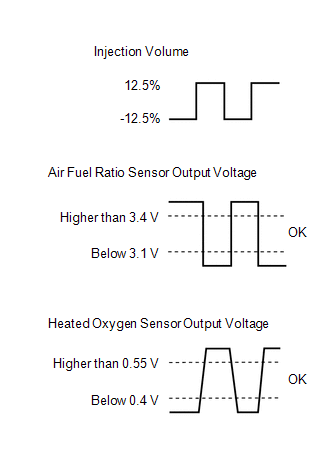
(h) Enter the following menus: Powertrain / Engine / Active Test / Control the Injection Volume for A/F sensor.
(i) Read the output voltage from the air fuel ratio sensor when increasing and decreasing the fuel injection volume.
Standard:
|
Techstream Display |
Injection Volume |
Specified Condition |
|---|---|---|
|
AFS Voltage B1S1 AFS Voltage B2S1 |
12.5% |
Air fuel ratio sensor output voltage is below 3.1 V |
|
-12.5% |
Air fuel ratio sensor output voltage is higher than 3.4 V |
HINT:
- The air fuel ratio sensor has an output delay of a few seconds and the heated oxygen sensor has a maximum output delay of approximately 20 seconds.
- If the air fuel ratio sensor is malfunctioning, after replacing it, check if engine starting trouble occurs again. If engine starting trouble occurs, replace the ECM. If engine starting trouble still occurs, proceed to step 72 and perform fuel system troubleshooting A (steps 96 to 103, fuel system troubleshooting B (steps 104 to 106), intake system troubleshooting (steps 107 to 109), and ignition system troubleshooting (steps 110 to 116), in that order.
-
Perform "Inspection After Repair" after replacing the air fuel ratio sensor (See page
).
| NG |
|
|
|
65. |
PERFORM SIMULATION TEST |
(a) Check if the idling speed is stable after starting the engine.
OK:
Speed is stable.
HINT:
- After replacing the fuel injector assembly or mass air flow meter, check if engine starting trouble occurs again. If engine starting trouble occurs, replace the ECM. If engine starting trouble still occurs, proceed to step 72 and perform fuel system troubleshooting A (steps 96 to 103, fuel system troubleshooting B (steps 104 to 106), intake system troubleshooting (steps 107 to 109), and ignition system troubleshooting (steps 110 to 116), in that order.
-
Perform "Inspection After Repair" after replacing the mass air flow meter (See page
).
| OK |
|
| NG |
|
|
66. |
CHECK FUEL PRESSURE |
(a) Check the fuel pressure (See page
).
| NG |
|
|
|
67. |
INSPECT SPARK PLUG |
(a) Inspect the spark plugs (See page
).
Result
|
Result |
Proceed to |
|---|---|
|
All cylinders are normal |
A |
|
One cylinder is abnormal*1 |
B |
|
All cylinders are abnormal*2, *3 |
C |
HINT:
- *1: If one cylinder is abnormal, replace the spark plug of that cylinder and inspect the ignition and fuel system for that cylinder. After performing repairs, check if engine starting trouble occurs again. If engine starting trouble still occurs, proceed to step 72 and perform fuel system troubleshooting A (steps 96 to 103, fuel system troubleshooting B (steps 104 to 106), intake system troubleshooting (steps 107 to 109), and ignition system troubleshooting (steps 110 to 116), in that order.
- *2: If all cylinders are abnormal, replace the spark plugs of all cylinders and check if engine starting trouble occurs again. If engine starting trouble still occurs, proceed to step 72 and perform fuel system troubleshooting A (steps 96 to 103, fuel system troubleshooting B (steps 104 to 106), intake system troubleshooting (steps 107 to 109), and ignition system troubleshooting (steps 110 to 116), in that order.
- *3: Engine starting trouble may occur if the vehicle is driven extremely short distances repeatedly.
-
Perform "Inspection After Repair" after replacing the spark plug (See page
).
| B |
|
| C |
|
|
|
68. |
CONFIRM VEHICLE CONDITION |
(a) Confirm the conditions present when the malfunction occurred based on the customer problem analysis.
Result
|
Problem Symptom |
Suspected Area |
Proceed to |
|---|---|---|
|
When the engine is stopped and a long time has passed, engine starting trouble occurs*1 |
Pressure regulator is stuck open |
A |
|
When the engine is stopped and approximately 15 to 120 minutes have passed, engine starting trouble occurs*2 |
Fuel injector assembly leaks |
B |
|
When the engine is stopped and approximately 2 to 3 minutes have passed, engine starting trouble occurs*3 |
Failure to maintain fuel pressure by pressure regulator |
A |
|
Condition other than above, or there is an inconsistency in the conditions present when engine starting trouble occurs |
- |
C*4 |
HINT:
*1: The pressure regulator may be stuck open. Attach a fuel pressure gauge and check the ability to maintain fuel pressure after stopping the engine.
*2: Fuel may be leaking from a fuel injector assembly.
*3: The pressure regulator may not be able to maintain the fuel pressure. Attach a fuel pressure gauge and check the ability to maintain fuel pressure after stopping the engine.
*4: From step 72, perform fuel system troubleshooting A (steps 96 to 103, fuel system troubleshooting B (steps 104 to 106), intake system troubleshooting (steps 107 to 109), and ignition system troubleshooting (steps 110 to 116), in that order.
| B |
|
| C |
|
|
|
69. |
CHECK FUEL PRESSURE |
HINT:
For the fuel pressure inspection, refer to the following procedures (See page
).
(a) Attach a fuel pressure gauge and check the fuel pressure after stopping the engine.
Result
|
Result |
Proceed to |
|---|---|
|
Less than 147 kPa (1.5 kgf/cm2) (5 minutes after stopping the engine) |
A |
|
147 kPa (1.5 kgf/cm2) or higher (5 minutes after stopping the engine) |
B*1 |
HINT:
- If the engine cannot be started, check the fuel pressure after cranking the engine.
- *1: From step 72, perform fuel system troubleshooting A (steps 96 to 103, fuel system troubleshooting B (steps 104 to 106), intake system troubleshooting (steps 107 to 109), and ignition system troubleshooting (steps 110 to 116), in that order.
-
Perform "Inspection After Repair" after replacing the fuel pump (See page
).
| A |
|
| B |
|
|
70. |
CHECK FUEL INJECTOR ASSEMBLY |
(a) Clean the inside of the surge tank with compressed air.
(b) After stopping the engine, measure the HC concentration inside the surge tank for 15 minutes.
Result
|
Result |
Proceed to |
|---|---|
|
4000 ppm or higher |
A |
|
Less than 4000 ppm |
B*1 |
HINT:
- If the concentration is 4000 ppm or higher, a fuel injector assembly may have a sealing problem.
- *1: From step 72, perform fuel system troubleshooting A (steps 96 to 103, fuel system troubleshooting B (steps 104 to 106), intake system troubleshooting (steps 107 to 109), and ignition system troubleshooting (steps 110 to 116), in that order.
-
Perform "Inspection After Repair" after replacing the fuel injector assembly (See page
).
| A |
|
| B |
|
|
71. |
PERFORM ACTIVE TEST USING TECHSTREAM (CONTROL THE FUEL PUMP/SPEED) |
(a) Connect the Techstream to the DLC3.
(b) Turn the ignition switch to ON.
(c) Turn the Techstream on.
(d) Enter the following menus: Powertrain / Engine / Active Test / Control the Fuel Pump/Speed.
(e) When performing the Active Test, check for fuel leakage from the fuel pipes.
Result
|
Result |
Proceed to |
|---|---|
|
Fuel leakage or signs of fuel leakage are present |
A |
|
No fuel leakage or signs of fuel leakage |
B |
HINT:
- Jiggle the wire harness and connector to increase the likelihood of detecting malfunctions that do not always occur.
- Check if the vehicle ran out of fuel, as engine starting trouble due to running out of fuel is also detected.
- If there are no fuel leaks, after inspecting the fuel pump control system, check if engine starting trouble occurs again. If engine starting trouble still occurs, proceed to step 72 and perform fuel system troubleshooting A (steps 96 to 103, fuel system troubleshooting B (steps 104 to 106), intake system troubleshooting (steps 107 to 109), and ignition system troubleshooting (steps 110 to 116), in that order.
| A |
|
REPAIR OR REPLACE FUEL LINE |
| B |
|
|
72. |
CHECK MALFUNCTION CONDITION |
(a) If the malfunction could not be identified during the inspection in steps 38, 39, 40 and 47, perform fuel system troubleshooting C (steps 73 to 77).
Result
|
Performed Step |
Troubleshooting by System |
Procedure |
Proceed to |
|---|---|---|---|
|
Steps 38, 39, 40 and 47 |
Fuel system troubleshooting C |
73 to 77 |
A |
(b) If the malfunction could not be identified during the inspection in step 45, perform ignition system troubleshooting (steps 78 to 84).
Result
|
Performed Step |
Troubleshooting by System |
Procedure |
Proceed to |
|---|---|---|---|
|
Step 45 |
Ignition system troubleshooting |
78 to 84 |
B |
(c) If the malfunction could not be identified during the inspection in steps 55, 56 and 57, perform intake air system troubleshooting (steps 85 to 87). If engine starting trouble still occurs, perform fuel system troubleshooting A (steps 88 to 95).
Result
|
Performed Step |
Troubleshooting by System |
Procedure |
Proceed to |
|---|---|---|---|
|
Step 55, 56, 57 |
Intake air system troubleshooting |
85 to 87 |
C |
|
Fuel system troubleshooting A |
88 to 95 |
(d) If the malfunction could not be identified during the inspection in steps 58, 59, 60, 61, 64, 65, 66, 67, 68, 69, 70 and 71, perform fuel system troubleshooting A (steps 96 to 103, fuel system troubleshooting B (steps 104 to 106), intake system troubleshooting (steps 107 to 109), and ignition system troubleshooting (steps 110 to 116), in that order.
Result
|
Performed Step |
Troubleshooting by System |
Procedure |
Proceed to |
|---|---|---|---|
|
Steps 58, 59, 60, 61, 64, 65, 66, 67, 68, 69, 70 and 71 |
Fuel system troubleshooting A |
97 to 104 |
D |
|
Fuel system troubleshooting B |
105 to 107 |
||
|
Intake air system troubleshooting |
108 to 110 |
||
|
Ignition system troubleshooting |
111 to 117 |
| B |
|
| C |
|
| D |
|
|
|
73. |
INSPECT FUEL INJECTOR ASSEMBLY |
(a) Inspect the fuel injector assembly (See page
).
HINT:
Perform "Inspection After Repair" after replacing the fuel injector assembly (See page
).
| NG |
|
|
|
74. |
CHECK TERMINAL VOLTAGE (FUEL INJECTOR ASSEMBLY POWER SOURCE) |
|
(a) Disconnect the fuel injector assembly connectors. |
|
(b) Turn the ignition switch to ON.
(c) Measure the voltage according to the value(s) in the table below.
Standard Voltage:
|
Tester Connection |
Switch Condition |
Specified Condition |
|---|---|---|
|
B7-2 - Body ground |
Ignition switch ON |
11 to 14 V |
|
B8-2 - Body ground |
Ignition switch ON |
11 to 14 V |
|
B9-2 - Body ground |
Ignition switch ON |
11 to 14 V |
|
B10-2 - Body ground |
Ignition switch ON |
11 to 14 V |
|
B11-2 - Body ground |
Ignition switch ON |
11 to 14 V |
|
B12-2 - Body ground |
Ignition switch ON |
11 to 14 V |
Text in Illustration
|
*a |
Front view of wire harness connector (to Fuel Injector Assembly) |
HINT:
- Jiggle the wire harness and connector to increase the likelihood of detecting malfunctions that do not always occur.
- Make sure there is not an excessive amount of force applied to the wire harness.
- A rapid decrease in engine speed may have been caused by a malfunction in all or multiple cylinders. (There may be an electrical malfunction in the wiring shared by all the cylinders.)
| NG |
|
|
|
75. |
CHECK HARNESS AND CONNECTOR (FUEL INJECTOR ASSEMBLY - ECM) |
(a) Disconnect the B7, B8, B9, B10, B11 and B12 fuel injector assembly connectors.
(b) Disconnect the B1 ECM connector.
(c) Measure the resistance according to the value(s) in the table below.
Standard Resistance:
|
Tester Connection |
Condition |
Specified Condition |
|---|---|---|
|
B7-1 - B1-86 (#10) |
Always |
Below 1 Ω |
|
B8-1 - B1-109 (#20) |
Always |
Below 1 Ω |
|
B9-1 - B1-85 (#30) |
Always |
Below 1 Ω |
|
B10-1 - B1-108 (#40) |
Always |
Below 1 Ω |
|
B11-1 - B1-84 (#50) |
Always |
Below 1 Ω |
|
B12-1 - B1-107 (#60) |
Always |
Below 1 Ω |
|
B7-1 or B1-86 (#10) - Body ground |
Always |
10 kΩ or higher |
|
B8-1 or B1-109 (#20) - Body ground |
Always |
10 kΩ or higher |
|
B9-1 or B1-85 (#30) - Body ground |
Always |
10 kΩ or higher |
|
B10-1 or B1-108 (#40) - Body ground |
Always |
10 kΩ or higher |
|
B11-1 or B1-84 (#50) - Body ground |
Always |
10 kΩ or higher |
|
B12-1 - B1-107 (#60) - Body ground |
Always |
10 kΩ or higher |
HINT:
- Jiggle the wire harness and connector to increase the likelihood of detecting malfunctions that do not always occur.
- Make sure there is not an excessive amount of force applied to the wire harness.
| NG |
|
REPAIR OR REPLACE HARNESS OR CONNECTOR |
|
|
76. |
INSPECT CRANKSHAFT POSITION SENSOR |
(a) Replace the crankshaft position sensor (See page
).
(b) Check the engine start operation.
OK:
Malfunction has been repaired successfully.
| OK |
|
END (CRANKSHAFT POSITION SENSOR IS DEFECTIVE) |
|
|
77. |
INSPECT VVT SENSOR |
(a) Replace the VVT sensor (See page
).
(b) Check the engine start operation.
OK:
Malfunction has been repaired successfully.
| OK |
|
END (VVT SENSOR IS DEFECTIVE) |
| NG |
|
|
78. |
CHECK CRANKSHAFT POSITION SENSOR |
(a) Check the tightening and installation condition of the crankshaft position sensor bolt.
(b) Check the connection of the crankshaft position sensor connector.
OK:
Sensor is installed correctly.
| NG |
|
|
|
79. |
CHECK VVT SENSOR |
(a) Check the tightening and installation condition of the VVT sensor bolt.
(b) Check the connection of the VVT sensor connector.
OK:
Sensor is installed correctly.
| NG |
|
|
|
80. |
CHECK HARNESS AND CONNECTOR (CRANKSHAFT POSITION SENSOR - ECM) |
(a) Disconnect the B15 crankshaft position sensor connector.
(b) Disconnect the B1 ECM connector.
(c) Measure the resistance according to the value(s) in the table below.
Standard Resistance:
|
Tester Connection |
Condition |
Specified Condition |
|---|---|---|
|
B15-1 - B1-110 (NE+) |
Always |
Below 1 Ω |
|
B15-2 - B1-111 (NE-) |
Always |
Below 1 Ω |
|
B15-1 or B1-110 (NE+) - Body ground |
Always |
10 kΩ or higher |
|
B15-2 or B1-111 (NE-) - Body ground |
Always |
10 kΩ or higher |
HINT:
- Jiggle the wire harness and connector to increase the likelihood of detecting malfunctions that do not always occur.
- Make sure there is not an excessive amount of force applied to the wire harness.
| NG |
|
REPAIR OR REPLACE HARNESS OR CONNECTOR |
|
|
81. |
CHECK HARNESS AND CONNECTOR (VVT SENSOR (FOR INTAKE SIDE) - ECM) |
(a) Disconnect the B16 and B17 VVT sensor (for intake side) connectors.
(b) Disconnect the B1 ECM connector.
(c) Measure the resistance according to the value(s) in the table below.
Standard Resistance:
|
Tester Connection |
Condition |
Specified Condition |
|---|---|---|
|
B16-1 (VVR+) - B1-90 (VV1+) |
Always |
Below 1 Ω |
|
B16-2 (VVR-) - B1-89 (VV1-) |
Always |
Below 1 Ω |
|
B16-3 (VC) - B1-67 (VCV1) |
Always |
Below 1 Ω |
|
B17-1 (VVL+) - B1-87 (VV2+) |
Always |
Below 1 Ω |
|
B17-2 (VVL-) - B1-88 (VV2-) |
Always |
Below 1 Ω |
|
B17-3 (VC) - B1-66 (VCV2) |
Always |
Below 1 Ω |
|
B16-1 (VVR+) or B1-90 (VV1+) - Body ground |
Always |
10 kΩ or higher |
|
B16-2 (VVR-) or B1-89 (VV1-) - Body ground |
Always |
10 kΩ or higher |
|
B16-3 (VC) or B1-67 (VCV1) - Body ground |
Always |
10 kΩ or higher |
|
B17-1 (VVL+) or B1-87 (VV2+) - Body ground |
Always |
10 kΩ or higher |
|
B17-2 (VVL-) or B1-88 (VV2-) - Body ground |
Always |
10 kΩ or higher |
|
B17-3 (VC) or B1-66 (VCV2) - Body ground |
Always |
10 kΩ or higher |
HINT:
- Jiggle the wire harness and connector to increase the likelihood of detecting malfunctions that do not always occur.
- Make sure there is not an excessive amount of force applied to the wire harness.
| NG |
|
REPAIR OR REPLACE HARNESS OR CONNECTOR |
|
|
82. |
CHECK HARNESS AND CONNECTOR (VVT SENSOR (FOR EXHAUST SIDE) - ECM) |
(a) Disconnect the B36 and B37 VVT sensor (for exhaust side) connectors.
(b) Disconnect the B1 ECM connector.
(c) Measure the resistance according to the value(s) in the table below.
Standard Resistance:
|
Tester Connection |
Condition |
Specified Condition |
|---|---|---|
|
B36-1 (EX+) - B1-69 (EV1+) |
Always |
Below 1 Ω |
|
B36-2 (EX-) - B1-89 (VV1-) |
Always |
Below 1 Ω |
|
B36-3 (VC2) - B1-67 (VCV1) |
Always |
Below 1 Ω |
|
B37-1 (EX+) - B1-64 (EV2+) |
Always |
Below 1 Ω |
|
B37-2 (EX-) - B1-89 (VV1-) |
Always |
Below 1 Ω |
|
B37-3 (VC2) - B1-67 (VCV1) |
Always |
Below 1 Ω |
|
B36-1 (EX+) or B1-69 (EV1+) - Body ground |
Always |
10 kΩ or higher |
|
B36-2 (EX-) or B1-89 (VV1-) - Body ground |
Always |
10 kΩ or higher |
|
B36-3 (VC2) or B1-67 (VCV1) - Body ground |
Always |
10 kΩ or higher |
|
B37-1 (EX+) or B1-64 (EV2+) - Body ground |
Always |
10 kΩ or higher |
|
B37-2 (EX-) or B1-89 (VV1-) - Body ground |
Always |
10 kΩ or higher |
|
B37-3 (VC2) or B1-67 (VCV1) - Body ground |
Always |
10 kΩ or higher |
HINT:
- Jiggle the wire harness and connector to increase the likelihood of detecting malfunctions that do not always occur.
- Make sure there is not an excessive amount of force applied to the wire harness.
| NG |
|
REPAIR OR REPLACE HARNESS OR CONNECTOR |
|
|
83. |
INSPECT CRANKSHAFT POSITION SENSOR |
(a) Replace the crankshaft position sensor (See page
).
(b) Check the engine start operation.
OK:
Malfunction has been repaired successfully.
| OK |
|
END (CRANKSHAFT POSITION SENSOR IS DEFECTIVE) |
|
|
84. |
INSPECT VVT SENSOR |
(a) Replace the VVT sensor (See page
).
(b) Check the engine start operation.
OK:
Malfunction has been repaired successfully.
| OK |
|
END (VVT SENSOR IS DEFECTIVE) |
| NG |
|
|
85. |
READ VALUE USING TECHSTREAM (ISC LEARNING VALUE) |
(a) Connect the Techstream to the DLC3.
(b) Turn the ignition switch to ON.
(c) Turn the Techstream on.
(d) Enter the following menus: Powertrain / Engine / Data List / ISC Learning Value.
(e) Start the engine and warm it up until the engine coolant temperature stabilizes with the A/C switch and all the accessory switches turned off.
Result
|
Data List Item |
Result |
Suspected Area |
Proceed to |
|---|---|---|---|
|
ISC Learning Value |
(engine displacement (liters) x 0.9) or more |
|
A |
|
Less than (engine displacement (liters) x 0.9) |
- |
B |
| B |
|
|
|
86. |
CHECK CYLINDER COMPRESSION PRESSURE |
(a) Check the compression (See page
).
HINT:
Perform "Inspection After Repair" after repairing or replacing the engine assembly (See page
).
| OK |
|
| NG |
|
REPAIR OR REPLACE ENGINE ASSEMBLY |
|
87. |
INSPECT ENGINE COOLANT TEMPERATURE SENSOR |
(a) Inspect the engine coolant temperature sensor (See page
).
HINT:
Perform "Inspection After Repair" after replacing the engine coolant temperature sensor (See page
).
| NG |
|
|
|
88. |
CHECK FUEL PRESSURE |
HINT:
For the fuel pressure inspection, refer to the following procedures (See page
).
(a) Attach a fuel pressure gauge and check the fuel pressure when cranking the engine and after stopping the engine.
Result
|
Vehicle State |
Specified Condition |
|---|---|
|
Cranking engine |
304 to 343 kPa (3.1 to 3.5 kgf/cm2) |
|
5 minutes after stopping engine |
147 kPa (1.5 kgf/cm2) or more |
| NG |
|
|
|
89. |
READ VALUE USING TECHSTREAM (LONG FT #1, FT #2) |
(a) Connect the Techstream to the DLC3.
(b) Turn the ignition switch to ON.
(c) Turn the Techstream on.
(d) Enter the following menus: Powertrain / Engine / Data List / Long FT #1 and Long FT #2.
Result
|
Data List Item |
Result |
Suspected Area |
Proceed to |
|---|---|---|---|
|
Long FT #1 Long FT #2 |
-15 to +15% |
|
A |
|
+15% or more, or less than -15% |
Fuel injector assembly |
B |
HINT:
Perform "Inspection After Repair" after replacing the fuel injector assembly (See page
).
| B |
|
|
|
90. |
PERFORM SIMULATION TEST |
(a) Check if the idling speed after starting the engine is currently stable and has always been stable in the past.
Result
|
Problem Symptom |
Suspected Area |
Proceed to |
|---|---|---|
|
Current unstable idling speed or history of unstable idling speed |
Crankshaft position sensor system |
A |
|
All current and past idling speeds are stable |
Fuel |
B |
HINT:
Through the customer problem analysis, confirm the fuel being used and the location at which the fuel was added to check if the malfunction is caused by the fuel in the vehicle.
| B |
|
REPLACE FUEL |
|
|
91. |
CHECK CRANKSHAFT POSITION SENSOR |
(a) Check the tightening and installation condition of the crankshaft position sensor bolt.
(b) Check the connection of the crankshaft position sensor connector.
OK:
Sensor is installed correctly.
| NG |
|
|
|
92. |
CHECK HARNESS AND CONNECTOR (CRANKSHAFT POSITION SENSOR - ECM) |
(a) Disconnect the B15 crankshaft position sensor connector.
(b) Disconnect the B1 ECM connector.
(c) Measure the resistance according to the value(s) in the table below.
Standard Resistance:
|
Tester Connection |
Condition |
Specified Condition |
|---|---|---|
|
B15-1 - B1-110 (NE+) |
Always |
Below 1 Ω |
|
B15-2 - B1-111 (NE-) |
Always |
Below 1 Ω |
|
B15-1 or B1-110 (NE+) - Body ground |
Always |
10 kΩ or higher |
|
B15-2 or B1-111 (NE-) - Body ground |
Always |
10 kΩ or higher |
HINT:
- Jiggle the wire harness and connector to increase the likelihood of detecting malfunctions that do not always occur.
- Make sure there is not an excessive amount of force applied to the wire harness.
| NG |
|
REPAIR OR REPLACE HARNESS OR CONNECTOR |
|
|
93. |
INSPECT CRANKSHAFT POSITION SENSOR |
(a) Replace the crankshaft position sensor (See page
).
(b) Check the engine start operation.
OK:
Malfunction has been repaired successfully.
| OK |
|
END (CRANKSHAFT POSITION SENSOR IS DEFECTIVE) |
| NG |
|
|
94. |
PERFORM ACTIVE TEST USING TECHSTREAM (CONTROL THE FUEL PUMP/SPEED) |
(a) Connect the Techstream to the DLC3.
(b) Turn the ignition switch to ON.
(c) Turn the Techstream on.
(d) Enter the following menus: Powertrain / Engine / Active Test / Control the Fuel Pump/Speed.
(e) When performing the Active Test, check for fuel leakage from the fuel pipes.
Result
|
Result |
Proceed to |
|---|---|
|
No fuel leakage or signs of fuel leakage |
A |
|
Fuel leakage or signs of fuel leakage are present |
B |
HINT:
- Jiggle the wire harness and connector to increase the likelihood of detecting malfunctions that do not always occur.
- When performing the Active Test, if there is no operating noise from the fuel pump, the fuel pump system may be malfunctioning.
- Check if the vehicle ran out of fuel, as engine starting trouble due to running out of fuel is also detected.
| B |
|
REPAIR OR REPLACE FUEL LINE |
|
|
95. |
INSPECT FUEL PUMP |
(a) Inspect the fuel pump (See page
).
HINT:
- Make sure there is no foreign matter such as iron particles on the fuel pump and no signs that the fuel pump was stuck.
- Make sure the internal connector is securely connected.
- Make sure the fuel pump filter is not clogged.
-
Perform "Inspection After Repair" after replacing the fuel pump (See page
).
| OK |
|
REPLACE FUEL PRESSURE REGULATOR |
| NG |
|
REPLACE FUEL PUMP |
|
96. |
CHECK FUEL PRESSURE |
HINT:
For the fuel pressure inspection, refer to the following procedures (See page
).
(a) Attach a fuel pressure gauge and check the fuel pressure after stopping the engine.
Result
|
Result |
Proceed to |
|---|---|
|
147 kPa (1.5 kgf/cm2) or higher (5 minutes after stopping the engine) |
A |
|
Less than 147 kPa (1.5 kgf/cm2) (5 minutes after stopping the engine) |
B |
| B |
|
|
|
97. |
READ VALUE USING TECHSTREAM (LONG FT #1, FT #2) |
(a) Connect the Techstream to the DLC3.
(b) Turn the ignition switch to ON.
(c) Turn the Techstream on.
(d) Enter the following menus: Powertrain / Engine / Data List / Long FT #1 and Long FT #2.
Result
|
Data List Item |
Result |
Suspected Area |
Proceed to |
|---|---|---|---|
|
Long FT #1 Long FT #2 |
-15 to +15% |
|
A |
|
+15% or more, or less than -15% |
Fuel injector assembly |
B |
HINT:
Perform "Inspection After Repair" after replacing the fuel injector assembly (See page
).
| B |
|
|
|
98. |
PERFORM SIMULATION TEST |
(a) Check if the idling speed after starting the engine is currently stable and has always been stable in the past.
Result
|
Problem Symptom |
Suspected Area |
Proceed to |
|---|---|---|
|
Current unstable idling speed or history of unstable idling speed |
Crankshaft position sensor system |
A |
|
All current and past idling speeds are stable |
Fuel |
B |
HINT:
Through the customer problem analysis, confirm the fuel being used and the location at which the fuel was added to check if the malfunction is caused by the fuel in the vehicle.
| B |
|
REPLACE FUEL |
|
|
99. |
CHECK CRANKSHAFT POSITION SENSOR |
(a) Check the tightening and installation condition of the crankshaft position sensor bolt.
(b) Check the connection of the crankshaft position sensor connector.
OK:
Sensor is installed correctly.
| NG |
|
|
|
100. |
CHECK HARNESS AND CONNECTOR (CRANKSHAFT POSITION SENSOR - ECM) |
(a) Disconnect the B15 crankshaft position sensor connector.
(b) Disconnect the B1 ECM connector.
(c) Measure the resistance according to the value(s) in the table below.
Standard Resistance:
|
Tester Connection |
Condition |
Specified Condition |
|---|---|---|
|
B15-1 - B1-110 (NE+) |
Always |
Below 1 Ω |
|
B15-2 - B1-111 (NE-) |
Always |
Below 1 Ω |
|
B15-1 or B1-110 (NE+) - Body ground |
Always |
10 kΩ or higher |
|
B15-2 or B1-111 (NE-) - Body ground |
Always |
10 kΩ or higher |
HINT:
- Jiggle the wire harness and connector to increase the likelihood of detecting malfunctions that do not always occur.
- Make sure there is not an excessive amount of force applied to the wire harness.
| NG |
|
REPAIR OR REPLACE HARNESS OR CONNECTOR |
|
|
101. |
INSPECT CRANKSHAFT POSITION SENSOR |
(a) Replace the crankshaft position sensor (See page
).
(b) Check the engine start operation.
OK:
Malfunction has been repaired successfully.
| OK |
|
END (CRANKSHAFT POSITION SENSOR IS DEFECTIVE) |
| NG |
|
|
102. |
PERFORM ACTIVE TEST USING TECHSTREAM (CONTROL THE FUEL PUMP/SPEED) |
(a) Connect the Techstream to the DLC3.
(b) Turn the ignition switch to ON.
(c) Turn the Techstream on.
(d) Enter the following menus: Powertrain / Engine / Active Test / Control the Fuel Pump/Speed.
(e) When performing the Active Test, check for fuel leakage from the fuel pipes.
Result
|
Result |
Proceed to |
|---|---|
|
Fuel leakage or signs of fuel leakage are present |
A |
|
No fuel leakage or signs of fuel leakage |
B |
HINT:
- Jiggle the wire harness and connector to increase the likelihood of detecting malfunctions that do not always occur.
- When performing the Active Test, if there is no operating noise from the fuel pump, the fuel pump system may be malfunctioning.
- Check if the vehicle ran out of fuel, as engine starting trouble due to running out of fuel is also detected.
| A |
|
REPAIR OR REPLACE FUEL LINE |
|
|
103. |
INSPECT FUEL PUMP |
(a) Inspect the fuel pump (See page
).
HINT:
- Make sure there is no foreign matter such as iron particles on the fuel pump and no signs that the fuel pump was stuck.
- Make sure the internal connector is securely connected.
- Make sure the fuel pump filter is not clogged.
-
Perform "Inspection After Repair" after replacing the fuel pump (See page
).
| NG |
|
|
|
104. |
INSPECT PURGE VSV |
|
(a) Disconnect the purge hose (on the canister side) of the purge VSV. Text in Illustration
|
|
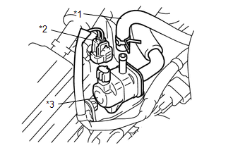
(b) Start the engine.
(c) Idle the engine.
(d) Disconnect the B22 connector of the purge VSV.
(e) Check if air flows through the purge VSV.
OK:
Air does not flow.
HINT:
When this inspection is performed, the MIL may illuminate. After finishing the inspection, check and clear DTCs (See page
).
| NG |
|
|
|
105. |
CHECK FUEL INJECTOR ASSEMBLY |
(a) Clean the inside of the surge tank with compressed air.
(b) After stopping the engine, measure the HC concentration inside the surge tank for 15 minutes.
Result
|
Result |
Proceed to |
|---|---|
|
4000 ppm or higher |
A |
|
Less than 4000 ppm |
B |
HINT:
- If the concentration is 4000 ppm or higher, a fuel injector assembly may have a sealing problem.
-
Perform "Inspection After Repair" after replacing the fuel injector assembly (See page
).
| A |
|
|
|
106. |
CHECK INTAKE VALVE |
(a) Check if carbon is on the intake valves.
Result
|
Result |
Proceed to |
|---|---|
|
Carbon present |
A |
|
No carbon present |
B |
| A |
|
CLEAN INTAKE VALVE |
|
|
107. |
READ VALUE USING TECHSTREAM (ISC LEARNING VALUE) |
(a) Connect the Techstream to the DLC3.
(b) Turn the ignition switch to ON.
(c) Turn the Techstream on.
(d) Enter the following menus: Powertrain / Engine / Data List / ISC Learning Value.
(e) Start the engine, turn off all accessory switches and warm up the engine until the engine coolant temperature stabilizes.
Result
|
Data List Item |
Result |
Suspected Area |
Proceed to |
|---|---|---|---|
|
ISC Learning Value |
(engine displacement (liters) x 0.9) or more |
|
A |
|
Less than (engine displacement (liters) x 0.9) |
- |
B |
| B |
|
|
|
108. |
CHECK CYLINDER COMPRESSION PRESSURE |
(a) Check the compression (See page
).
HINT:
Perform "Inspection After Repair" after repairing or replacing the engine assembly (See page
).
| OK |
|
| NG |
|
REPAIR OR REPLACE ENGINE ASSEMBLY |
|
109. |
INSPECT ENGINE COOLANT TEMPERATURE SENSOR |
(a) Inspect the engine coolant temperature sensor (See page
).
HINT:
Perform "Inspection After Repair" after replacing the engine coolant temperature sensor (See page
).
| NG |
|
|
|
110. |
CHECK CRANKSHAFT POSITION SENSOR |
(a) Check the tightening and installation condition of the crankshaft position sensor bolt.
(b) Check the connection of the crankshaft position sensor connector.
OK:
Sensor is installed correctly.
| NG |
|
|
|
111. |
CHECK VVT SENSOR |
(a) Check the tightening and installation condition of the VVT sensor bolt.
(b) Check the connection of the VVT sensor connector.
OK:
Sensor is installed correctly.
| NG |
|
|
|
112. |
CHECK HARNESS AND CONNECTOR (CRANKSHAFT POSITION SENSOR - ECM) |
(a) Disconnect the B15 crankshaft position sensor connector.
(b) Disconnect the B1 ECM connector.
(c) Measure the resistance according to the value(s) in the table below.
Standard Resistance:
|
Tester Connection |
Condition |
Specified Condition |
|---|---|---|
|
B15-1 - B1-110 (NE+) |
Always |
Below 1 Ω |
|
B15-2 - B1-111 (NE-) |
Always |
Below 1 Ω |
|
B15-1 or B1-110 (NE+) - Body ground |
Always |
10 kΩ or higher |
|
B15-2 or B1-111 (NE-) - Body ground |
Always |
10 kΩ or higher |
HINT:
- Jiggle the wire harness and connector to increase the likelihood of detecting malfunctions that do not always occur.
- Make sure there is not an excessive amount of force applied to the wire harness.
| NG |
|
REPAIR OR REPLACE HARNESS OR CONNECTOR |
|
|
113. |
CHECK HARNESS AND CONNECTOR (VVT SENSOR (FOR INTAKE SIDE) - ECM) |
(a) Disconnect the B16 and B17 VVT sensor (for intake side) connectors.
(b) Disconnect the B1 ECM connector.
(c) Measure the resistance according to the value(s) in the table below.
Standard Resistance:
|
Tester Connection |
Condition |
Specified Condition |
|---|---|---|
|
B16-1 (VVR+) - B1-90 (VV1+) |
Always |
Below 1 Ω |
|
B16-2 (VVR-) - B1-89 (VV1-) |
Always |
Below 1 Ω |
|
B16-3 (VC) - B1-67 (VCV1) |
Always |
Below 1 Ω |
|
B17-1 (VVL+) - B1-87 (VV2+) |
Always |
Below 1 Ω |
|
B17-2 (VVL-) - B1-88 (VV2-) |
Always |
Below 1 Ω |
|
B17-3 (VC) - B1-66 (VCV2) |
Always |
Below 1 Ω |
|
B16-1 (VVR+) or B1-90 (VV1+) - Body ground |
Always |
10 kΩ or higher |
|
B16-2 (VVR-) or B1-89 (VV1-) - Body ground |
Always |
10 kΩ or higher |
|
B16-3 (VC) or B1-67 (VCV1) - Body ground |
Always |
10 kΩ or higher |
|
B17-1 (VVL+) or B1-87 (VV2+) - Body ground |
Always |
10 kΩ or higher |
|
B17-2 (VVL-) or B1-88 (VV2-) - Body ground |
Always |
10 kΩ or higher |
|
B17-3 (VC) or B1-66 (VCV2) - Body ground |
Always |
10 kΩ or higher |
HINT:
- Jiggle the wire harness and connector to increase the likelihood of detecting malfunctions that do not always occur.
- Make sure there is not an excessive amount of force applied to the wire harness.
| NG |
|
REPAIR OR REPLACE HARNESS OR CONNECTOR |
|
|
114. |
CHECK HARNESS AND CONNECTOR (VVT SENSOR (FOR EXHAUST SIDE) - ECM) |
(a) Disconnect the B36 and B37 VVT sensor (for exhaust side) connectors.
(b) Disconnect the B1 ECM connector.
(c) Measure the resistance according to the value(s) in the table below.
Standard Resistance:
|
Tester Connection |
Condition |
Specified Condition |
|---|---|---|
|
B36-1 (EX+) - B1-69 (EV1+) |
Always |
Below 1 Ω |
|
B36-2 (EX-) - B1-89 (VV1-) |
Always |
Below 1 Ω |
|
B36-3 (VC2) - B1-67 (VCV1) |
Always |
Below 1 Ω |
|
B37-1 (EX+) - B1-64 (EV2+) |
Always |
Below 1 Ω |
|
B37-2 (EX-) - B1-89 (VV1-) |
Always |
Below 1 Ω |
|
B37-3 (VC2) - B1-67 (VCV1) |
Always |
Below 1 Ω |
|
B36-1 (EX+) or B1-69 (EV1+) - Body ground |
Always |
10 kΩ or higher |
|
B36-2 (EX-) or B1-89 (VV1-) - Body ground |
Always |
10 kΩ or higher |
|
B36-3 (VC2) or B1-67 (VCV1) - Body ground |
Always |
10 kΩ or higher |
|
B37-1 (EX+) or B1-64 (EV2+) - Body ground |
Always |
10 kΩ or higher |
|
B37-2 (EX-) or B1-89 (VV1-) - Body ground |
Always |
10 kΩ or higher |
|
B37-3 (VC2) or B1-67 (VCV1) - Body ground |
Always |
10 kΩ or higher |
HINT:
- Jiggle the wire harness and connector to increase the likelihood of detecting malfunctions that do not always occur.
- Make sure there is not an excessive amount of force applied to the wire harness.
| NG |
|
REPAIR OR REPLACE HARNESS OR CONNECTOR |
|
|
115. |
INSPECT CRANKSHAFT POSITION SENSOR |
(a) Replace the crankshaft position sensor (See page
).
(b) Check the engine start operation.
OK:
Malfunction has been repaired successfully.
| OK |
|
END (CRANKSHAFT POSITION SENSOR IS DEFECTIVE) |
|
|
116. |
INSPECT VVT SENSOR |
(a) Replace the VVT sensor (See page
).
(b) Check the engine start operation.
OK:
Malfunction has been repaired successfully.
| OK |
|
END (VVT SENSOR IS DEFECTIVE) |
| NG |
|
|
|
|