| Last Modified: 08-28-2024 | 6.11:8.1.0 | Doc ID: RM100000000VIBM |
| Model Year Start: 2016 | Model: Sienna | Prod Date Range: [12/2015 - 08/2016] |
| Title: 2GR-FE (ENGINE CONTROL): SFI SYSTEM: VC Output Circuit; 2016 MY Sienna [12/2015 - 08/2016] | ||
|
VC Output Circuit |
DESCRIPTION
The ECM constantly uses 5 V from the battery voltages supplied to the +B (BATT) terminal to operate the microprocessor. The ECM also provides this power to the sensors through the VC output circuit.
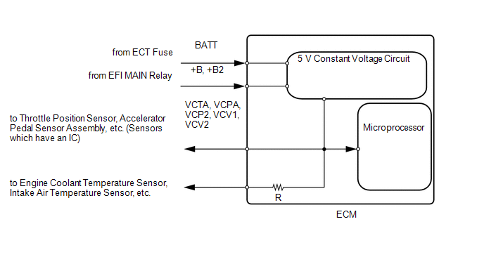
When the VC circuit is shorted, the microprocessor in the ECM and sensors that are supplied power through the VC circuit are inactivated because the power is not supplied from the VC circuit. Under this condition, the system does not start up and the MIL does not illuminate even if the system malfunctions.
HINT:
Under normal conditions, the MIL is illuminated for several seconds when the ignition switch is first turned ON. The MIL goes off when the engine is started.
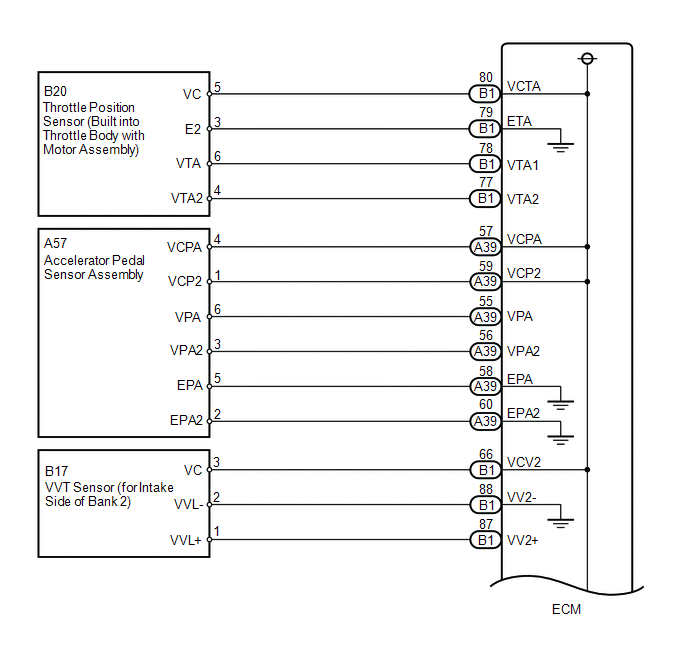
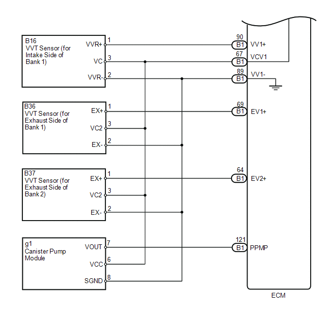
WIRING DIAGRAM
CAUTION / NOTICE / HINT
HINT:
-
Bank 1 refers to the bank that includes the No. 1 cylinder*.
*: The No. 1 cylinder is the cylinder which is farthest from the transaxle.
- Bank 2 refers to the bank that does not include the No. 1 cylinder.
PROCEDURE
|
1. |
CHECK MIL |
(a) Check that the Malfunction Indicator Lamp (MIL) illuminates when turning the ignition switch to ON.
OK:
MIL lights up.
| OK |

|
PROCEED TO NEXT SUSPECTED AREA SHOWN IN PROBLEM SYMPTOMS TABLE |
|

|
2. |
CHECK CONNECTION BETWEEN TECHSTREAM AND ECM |
(a) Connect the Techstream to the DLC3.
(b) Turn the ignition switch to ON.
(c) Turn the Techstream on.
(d) Check the communication between the Techstream and ECM.
Result
|
Result |
Proceed to |
|---|---|
|
Communication is not possible |
A |
|
Communication is possible |
B |
| B |
|
|
|
3. |
CHECK MIL (THROTTLE POSITION SENSOR) |
(a) Disconnect the B20 throttle body with motor assembly connector.
(b) Turn the ignition switch to ON.
(c) Check the MIL.
Result
|
Result |
Proceed to |
|---|---|
|
MIL does not illuminate |
A |
|
MIL illuminates |
B |
HINT:
Perform "Inspection After Repair" after repairing the throttle body with motor assembly (See page
![2016 MY Sienna [12/2015 - 08/2016]; 2GR-FE (ENGINE CONTROL): SFI SYSTEM: INITIALIZATION](/t3Portal/stylegraphics/info.gif) ).
).
| B |
|
|
|
4. |
CHECK MIL (ACCELERATOR PEDAL SENSOR ASSEMBLY) |
(a) Disconnect the A57 accelerator pedal sensor assembly connector.
(b) Turn the ignition switch to ON.
(c) Check the MIL.
Result
|
Result |
Proceed to |
|---|---|
|
MIL does not illuminate |
A |
|
MIL illuminates |
B |
| B |
|
|
|
5. |
CHECK MIL (VVT SENSOR (FOR INTAKE SIDE OF BANK 1)) |
(a) Disconnect the B16 VVT sensor (for intake side of bank 1) connector.
(b) Turn the ignition switch to ON.
(c) Check the MIL.
Result
|
Result |
Proceed to |
|---|---|
|
MIL illuminates |
A |
|
MIL does not illuminate |
B |
| B |
|
|
|
6. |
CHECK MIL (VVT SENSOR (FOR INTAKE SIDE OF BANK 2)) |
(a) Disconnect the B17 VVT sensor (for intake side of bank 2) connector.
(b) Turn the ignition switch to ON.
(c) Check the MIL.
Result
|
Result |
Proceed to |
|---|---|
|
MIL illuminates |
A |
|
MIL does not illuminate |
B |
| B |
|
|
|
7. |
CHECK MIL (VVT SENSOR (FOR EXHAUST OF SIDE BANK 1)) |
(a) Disconnect the B36 VVT sensor (for exhaust side of bank 1) connector.
(b) Turn the ignition switch to ON.
(c) Check the MIL.
Result
|
Result |
Proceed to |
|---|---|
|
MIL illuminates |
A |
|
MIL does not illuminate |
B |
| B |
|
|
|
8. |
CHECK MIL (VVT SENSOR (FOR EXHAUST SIDE OF BANK 2)) |
(a) Disconnect the B37 VVT sensor (for exhaust side of bank 2) connector.
(b) Turn the ignition switch to ON.
(c) Check the MIL.
Result
|
Result |
Proceed to |
|---|---|
|
MIL illuminates |
A |
|
MIL does not illuminate |
B |
| B |
|
|
|
9. |
CHECK MIL (CANISTER PUMP MODULE) |
(a) Disconnect the g1 canister pump module connector.
(b) Turn the ignition switch to ON.
(c) Check the MIL.
Result
|
Result |
Proceed to |
|---|---|
|
MIL illuminates |
A |
|
MIL does not illuminate |
B |
| B |
|
|
|
10. |
CHECK HARNESS AND CONNECTOR (THROTTLE BODY WITH MOTOR ASSEMBLY - ECM) |
(a) Disconnect the B20 throttle body with motor assembly connector.
(b) Disconnect the B1 ECM connector.
(c) Measure the resistance according to the value(s) in the table below.
Standard Resistance:
|
Tester Connection |
Condition |
Specified Condition |
|---|---|---|
|
B1-80 (VCTA) or B20-5 (VC) - Body ground |
Always |
10 kΩ or higher |
| NG |
|
REPAIR OR REPLACE HARNESS OR CONNECTOR |
|
|
11. |
CHECK HARNESS AND CONNECTOR (ACCELERATOR PEDAL SENSOR ASSEMBLY - ECM) |
(a) Disconnect the A57 accelerator pedal sensor assembly connector.
(b) Disconnect the B1 ECM connector.
(c) Measure the resistance according to the value(s) in the table below.
Standard Resistance:
|
Tester Connection |
Condition |
Specified Condition |
|---|---|---|
|
A57-1 (VCP2) or A39-59 (VCP2) - Body ground |
Always |
10 kΩ or higher |
|
A57-4 (VCPA) or A39-57 (VCPA) - Body ground |
Always |
10 kΩ or higher |
| NG |
|
REPAIR OR REPLACE HARNESS OR CONNECTOR |
|
|
12. |
CHECK HARNESS AND CONNECTOR (VVT SENSOR (FOR INTAKE SIDE OF BANK 2) - ECM) |
(a) Disconnect the B16 VVT sensor (for intake side of bank 2) connector.
(b) Disconnect the B1 ECM connector.
(c) Measure the resistance according to the value(s) in the table below.
Standard Resistance:
|
Tester Connection |
Condition |
Specified Condition |
|---|---|---|
|
B17-3 (VC) or B1-66 (VCV2) - Body ground |
Always |
10 kΩ or higher |
| NG |
|
REPAIR OR REPLACE HARNESS OR CONNECTOR |
|
|
13. |
CHECK HARNESS AND CONNECTOR (VCV1 CIRCUIT) |
(a) Disconnect the B17 VVT sensor (for intake side of bank 1) connector.
(b) Disconnect the B36 VVT sensor (for exhaust side of bank 1) connector.
(c) Disconnect the B37 VVT sensor (for exhaust side of bank 2) connector.
(d) Disconnect the g1 canister pump module connector.
(e) Disconnect the B1 ECM connector.
(f) Measure the resistance according to the value(s) in the table below.
Standard Resistance:
|
Tester Connection |
Condition |
Specified Condition |
|---|---|---|
|
B1-67 (VCV1) - Body ground |
Always |
10 kΩ or higher |
| OK |
|
| NG |
|
REPAIR OR REPLACE HARNESS OR CONNECTOR |
|
|
|