| Last Modified: 08-28-2024 | 6.11:8.1.0 | Doc ID: RM100000000VIB1 |
| Model Year Start: 2016 | Model: Sienna | Prod Date Range: [12/2015 - 08/2016] |
| Title: 2GR-FE (ENGINE CONTROL): SFI SYSTEM: Fuel Injector Circuit; 2016 MY Sienna [12/2015 - 08/2016] | ||
|
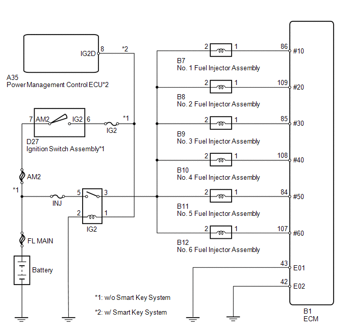
Fuel Injector Circuit |
DESCRIPTION
The fuel injector assemblies are located on the intake manifold. They inject fuel into the cylinders based on signals from the ECM.
WIRING DIAGRAM
CAUTION / NOTICE / HINT
NOTICE:
Inspect the fuses for circuits related to this system before performing the following inspection procedure.
PROCEDURE
|
1. |
CHECK FUEL INJECTOR ASSEMBLY (POWER SOURCE) |
|
(a) Disconnect the fuel injector assembly connectors. |
|
(b) Turn the ignition switch to ON.
(c) Measure the voltage according to the value(s) in the table below.
Standard Voltage:
|
Tester Connection |
Switch Condition |
Specified Condition |
|---|---|---|
|
B7-2 - Body ground |
Ignition switch ON |
11 to 14 V |
|
B8-2 - Body ground |
Ignition switch ON |
11 to 14 V |
|
B9-2 - Body ground |
Ignition switch ON |
11 to 14 V |
|
B10-2 - Body ground |
Ignition switch ON |
11 to 14 V |
|
B11-2 - Body ground |
Ignition switch ON |
11 to 14 V |
|
B12-2 - Body ground |
Ignition switch ON |
11 to 14 V |
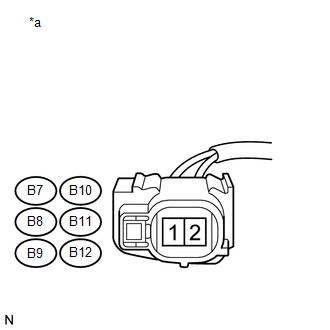
Text in Illustration
|
*a |
Front view of wire harness connector (to Fuel Injector Assembly) |
| NG |

|
|

|
2. |
INSPECT FUEL INJECTOR ASSEMBLY |
(a) Inspect the fuel injector assembly (See page
![2016 MY Sienna [12/2015 - 08/2016]; 2GR-FE FUEL: FUEL INJECTOR: INSPECTION](/t3Portal/stylegraphics/info.gif) ).
).
HINT:
Perform "Inspection After Repair" after replacing the fuel injector assembly (See page
).
| NG |
|
|
|
3. |
CHECK HARNESS AND CONNECTOR (FUEL INJECTOR ASSEMBLY - ECM) |
(a) Disconnect the B7, B8, B9, B10, B11 and B12 fuel injector assembly connectors.
(b) Disconnect the B1 ECM connector.
(c) Measure the resistance according to the value(s) in the table below.
Standard Resistance:
|
Tester Connection |
Condition |
Specified Condition |
|---|---|---|
|
B7-1 - B1-86 (#10) |
Always |
Below 1 Ω |
|
B8-1 - B1-109 (#20) |
Always |
Below 1 Ω |
|
B9-1 - B1-85 (#30) |
Always |
Below 1 Ω |
|
B10-1 - B1-108 (#40) |
Always |
Below 1 Ω |
|
B11-1 - B1-84 (#50) |
Always |
Below 1 Ω |
|
B12-1 - B1-107 (#60) |
Always |
Below 1 Ω |
|
B7-1 or B1-86 (#10) - Body ground |
Always |
10 kΩ or higher |
|
B8-1 or B1-109 (#20) - Body ground |
Always |
10 kΩ or higher |
|
B9-1 or B1-85 (#30) - Body ground |
Always |
10 kΩ or higher |
|
B10-1 or B1-108 (#40) - Body ground |
Always |
10 kΩ or higher |
|
B11-1 or B1-84 (#50) - Body ground |
Always |
10 kΩ or higher |
|
B12-1 or B1-107 (#60) - Body ground |
Always |
10 kΩ or higher |
| OK |
|
PROCEED TO NEXT SUSPECTED AREA SHOWN IN PROBLEM SYMPTOMS TABLE |
| NG |
|
REPAIR OR REPLACE HARNESS OR CONNECTOR |
|
4. |
CHECK HARNESS AND CONNECTOR (IG2 RELAY - FUEL INJECTOR ASSEMBLY) |
(a) Disconnect the B7, B8, B9, B10, B11 and B12 fuel injector assembly connectors.
(b) Remove the IG2 relay from the engine room relay block.
(c) Measure the resistance according to the value(s) in the table below.
Standard Resistance:
|
Tester Connection |
Condition |
Specified Condition |
|---|---|---|
|
B7-2 - 3 (IG2 relay holder) |
Always |
Below 1 Ω |
|
B8-2 - 3 (IG2 relay holder) |
Always |
Below 1 Ω |
|
B9-2 - 3 (IG2 relay holder) |
Always |
Below 1 Ω |
|
B10-2 - 3 (IG2 relay holder) |
Always |
Below 1 Ω |
|
B11-2 - 3 (IG2 relay holder) |
Always |
Below 1 Ω |
|
B12-2 - 3 (IG2 relay holder) |
Always |
Below 1 Ω |
|
B7-2 or 3 (IG2 relay holder) - Body ground |
Always |
10 kΩ or higher |
|
B8-2 or 3 (IG2 relay holder) - Body ground |
Always |
10 kΩ or higher |
|
B9-2 or 3 (IG2 relay holder) - Body ground |
Always |
10 kΩ or higher |
|
B10-2 or 3 (IG2 relay holder) - Body ground |
Always |
10 kΩ or higher |
|
B11-2 or 3 (IG2 relay holder) - Body ground |
Always |
10 kΩ or higher |
|
B12-2 or 3 (IG2 relay holder) - Body ground |
Always |
10 kΩ or higher |
| OK |
|
| NG |
|
REPAIR OR REPLACE HARNESS OR CONNECTOR |
|
|
|