- Open or short in camshaft timing oil control valve assembly (for intake side of bank 1) circuit
- Camshaft timing oil control valve assembly (for intake side of bank 1)
- ECM
| Last Modified: 08-28-2024 | 6.11:8.1.0 | Doc ID: RM100000000VIB0 |
| Model Year Start: 2016 | Model: Sienna | Prod Date Range: [12/2015 - 08/2016] |
| Title: 2GR-FE (ENGINE CONTROL): SFI SYSTEM: P0010,P0020; Camshaft Position "A" Actuator Circuit (Bank 1); 2016 MY Sienna [12/2015 - 08/2016] | ||
|
DTC |
P0010 |
Camshaft Position "A" Actuator Circuit (Bank 1) |
|
DTC |
P0020 |
Camshaft Position "A" Actuator Circuit (Bank 2) |
DESCRIPTION
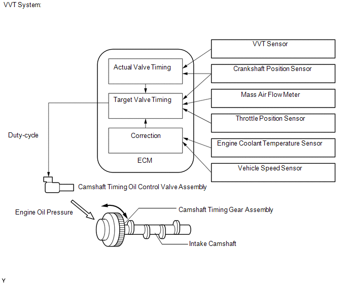
The Variable Valve Timing (VVT) system includes the ECM, camshaft timing oil control valve assembly and camshaft timing gear assembly. The ECM sends a target duty-cycle control signal to the camshaft timing oil control valve assembly. This control signal regulates the oil pressure supplied to the camshaft timing gear assembly. Camshaft timing control is performed according to engine operating conditions such as intake air volume, throttle valve position and engine coolant temperature. The ECM controls the camshaft timing oil control valve assembly, based on the signals transmitted from several sensors. The camshaft timing gear assembly regulates the intake camshaft angle using oil pressure through the camshaft timing oil control valve assembly. As a result, the relative positions of the camshaft and crankshaft are optimized, the engine torque and fuel economy improve, and the exhaust emissions decrease under overall driving conditions. The ECM detects the actual intake valve timing using signals from the VVT sensor and crankshaft position sensor, and performs feedback control. This is how the target intake valve timing is verified by the ECM.
|
DTC No. |
DTC Detection Condition |
Trouble Area |
|---|---|---|
|
P0010 |
Open or short in camshaft timing oil control valve assembly (for intake side of bank 1) circuit (1 trip detection logic) |
|
|
P0020 |
Open or short in camshaft timing oil control valve assembly (for intake side of bank 2) circuit (1 trip detection logic) |
|
MONITOR DESCRIPTION
This DTC is designed to detect an open or short in the camshaft timing oil control valve assembly (for intake side) circuit. If the oil control valve duty-cycle is excessively high or low while the engine is running, the ECM will illuminate the MIL and store the DTC.
MONITOR STRATEGY
|
Related DTCs |
P0010: Camshaft timing oil control valve assembly (for intake side of bank 1) range check P0020: Camshaft timing oil control valve assembly (for intake side of bank 2) range check |
|
Required sensors / components (Main) |
Camshaft timing oil control valve assembly (for intake side) |
|
Required sensors / components (Related) |
- |
|
Frequency of operation |
Continuous |
|
Duration |
1 second |
|
MIL operation |
Immediately |
|
Sequence of operation |
None |
TYPICAL ENABLING CONDITIONS
All
|
Monitor runs whenever following DTCs are not present |
None |
|
All of the following conditions are met: |
- |
|
Starter |
OFF |
|
Ignition switch |
ON |
|
Time after ignition switch off to ON |
0.5 seconds or more |
Case 1
|
One of the following conditions is met |
Conditions A or B |
|
A. All of the following conditions are met |
- |
|
Battery voltage |
11 V or higher, and less than 13 V |
|
Target duty cycle |
Less than 70% |
|
B. All of the following conditions are met |
- |
|
Battery voltage |
13 V or higher |
|
Target duty cycle |
Less than 80% |
Case 2
|
Current cut status |
Not cut |
TYPICAL MALFUNCTION THRESHOLDS
Case 1
|
Output duty cycle |
100% or more |
Case 2
|
Output duty cycle |
3% or less |
COMPONENT OPERATING RANGE
|
Output duty cycle |
More than 3%, and less than 100% |
CONFIRMATION DRIVING PATTERN
- Connect the Techstream to the DLC3.
- Turn the ignition switch to ON and turn the Techstream on.
-
Clear DTCs (even if no DTCs are stored, perform the clear DTC procedure) (See page
![2016 MY Sienna [12/2015 - 08/2016]; 2GR-FE (ENGINE CONTROL): SFI SYSTEM: DTC CHECK / CLEAR](/t3Portal/stylegraphics/info.gif) ).
).
- Turn the ignition switch off and wait for at least 30 seconds.
- Turn the ignition switch to ON and turn the Techstream on.
- Wait 5 seconds.
- Enter the following menus: Powertrain / Engine / Trouble Code.
-
Read pending DTCs.
HINT:
- If a pending DTC is output, the system is malfunctioning.
- If a pending DTC is not output, perform the following procedure.
- Enter the following menus: Powertrain / Engine / Utility / All Readiness.
- Input the DTC: P0010 or P0020.
-
Check the DTC judgment result.
Techstream Display
Description
NORMAL
- DTC judgment completed
- System normal
ABNORMAL
- DTC judgment completed
- System abnormal
INCOMPLETE
- DTC judgment not completed
- Perform driving pattern after confirming DTC enabling conditions
N/A
- Unable to perform DTC judgment
- Number of DTCs which do not fulfill DTC preconditions has reached ECU's memory limit
HINT:
If the judgment result shows ABNORMAL, the system has a malfunction.
-
If the test result is INCOMPLETE or N/A and no pending DTC is output, perform a universal trip and check for permanent DTCs (See page
).
HINT:
- If a permanent DTC is output, the system is malfunctioning.
- If no permanent DTC is output, the system is normal.
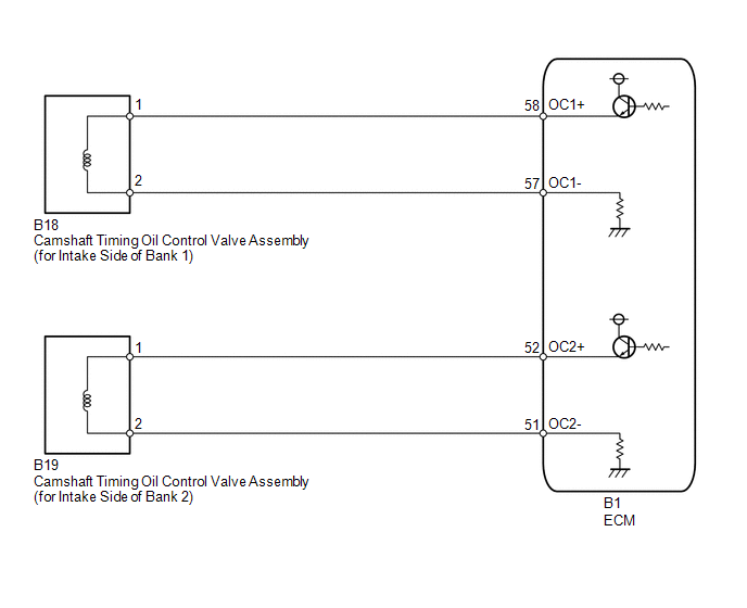
WIRING DIAGRAM
CAUTION / NOTICE / HINT
HINT:
- If DTC P0010 is output, check the VVT system (for intake camshaft of bank 1) circuit.
- If DTC P0020 is output, check the VVT system (for intake camshaft of bank 2) circuit.
-
Bank 1 refers to the bank that includes the No. 1 cylinder*.
*: The No. 1 cylinder is the cylinder which is farthest from the transaxle.
- Bank 2 refers to the bank that does not include the No. 1 cylinder.
- Read freeze frame data using the Techstream. The ECM records vehicle and driving condition information as freeze frame data the moment a DTC is stored. When troubleshooting, freeze frame data can help determine if the vehicle was moving or stationary, if the engine was warmed up or not, if the air fuel ratio was lean or rich, and other data from the time the malfunction occurred.
PROCEDURE
|
1. |
CHECK DTC (DTC P0010 OR P0020) |
(a) Connect the Techstream to the DLC3.
(b) Turn the ignition switch to ON.
(c) Turn the Techstream on.
(d) Enter the following menus: Powertrain / Engine / Trouble Codes.
(e) Read DTCs.
Result
|
Result |
Proceed to |
|---|---|
|
DTC P0010 is output |
A |
|
DTC P0020 is output |
B |
| B |

|
|

|
2. |
PERFORM ACTIVE TEST USING TECHSTREAM (CONTROL THE VVT SYSTEM (BANK 1)) |
(a) Check the engine speed while operating the camshaft timing oil control valve assembly (for intake side of bank 1) using the Techstream (See page
).
| OK |
|
| NG |
|
|
3. |
PERFORM ACTIVE TEST USING TECHSTREAM (CONTROL THE VVT SYSTEM (BANK 2)) |
(a) Check the engine speed while operating the camshaft timing oil control valve assembly (for intake side of bank 2) using the Techstream (See page
).
| OK |
|
|
|
4. |
INSPECT CAMSHAFT TIMING OIL CONTROL VALVE ASSEMBLY (FOR INTAKE SIDE) |
(a) Inspect the camshaft timing oil control valve assembly (for intake side) (See page
).
| NG |
|
REPLACE CAMSHAFT TIMING OIL CONTROL VALVE ASSEMBLY (FOR INTAKE SIDE) |
|
|
5. |
CHECK HARNESS AND CONNECTOR (CAMSHAFT TIMING OIL CONTROL VALVE ASSEMBLY (FOR INTAKE SIDE) - ECM) |
(a) Disconnect the camshaft timing oil control valve assembly (for intake side) connector.
(b) Disconnect the ECM connector.
(c) Measure the resistance according to the value(s) in the table below.
Standard Resistance (Check for Open):
|
Tester Connection |
Condition |
Specified Condition |
|---|---|---|
|
B18-1 - B1-58 (OC1+) |
Always |
Below 1 Ω |
|
B18-2 - B1-57 (OC1-) |
Always |
Below 1 Ω |
|
B19-1 - B1-52 (OC2+) |
Always |
Below 1 Ω |
|
B19-2 - B1-51 (OC2-) |
Always |
Below 1 Ω |
Standard Resistance (Check for Short):
|
Tester Connection |
Condition |
Specified Condition |
|---|---|---|
|
B18-1 or B1-58 (OC1+) - Body ground |
Always |
10 kΩ or higher |
|
B18-2 or B1-57 (OC1-) - Body ground |
Always |
10 kΩ or higher |
|
B19-1 or B1-52 (OC2+) - Body ground |
Always |
10 kΩ or higher |
|
B19-2 or B1-51 (OC2-) - Body ground |
Always |
10 kΩ or higher |
| OK |
|
| NG |
|
REPAIR OR REPLACE HARNESS OR CONNECTOR |
|
|
|