- (a) Vehicle speed is 20 km/h (12.43 mph) or more.
- (b) Engine speed is 1000 rpm or more.
- (c) STA signal is on.
| Last Modified: 08-28-2024 | 6.11:8.1.0 | Doc ID: RM100000000VIAS |
| Model Year Start: 2016 | Model: Sienna | Prod Date Range: [12/2015 - 08/2016] |
| Title: 2GR-FE (ENGINE CONTROL): SFI SYSTEM: P0617; Starter Relay Circuit High; 2016 MY Sienna [12/2015 - 08/2016] | ||
|
DTC |
P0617 |
Starter Relay Circuit High |
DESCRIPTION
While the engine is being cranked, positive battery voltage is applied to terminal STA of the ECM.
If the ECM detects the starter (STA) signal while the vehicle is being driven, it determines that there is a malfunction in the STA circuit. The ECM then illuminates the MIL and stores the DTC.
This monitor runs when the vehicle is driven at 20 km/h (12.43 mph) or more for over 20 seconds.
|
DTC No. |
DTC Detection Condition |
Trouble Area |
|---|---|---|
|
P0617 |
When conditions (a), (b) and (c) are met, positive (+B) battery voltage 10.5 V or more is applied to ECM for 20 seconds (1 trip detection logic): |
|
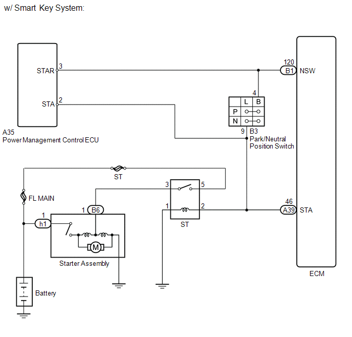
*1: w/ Smart Key System
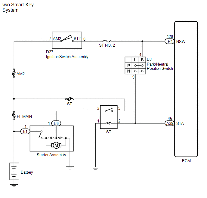
*2: w/o Smart Key System
MONITOR STRATEGY
|
Related DTCs |
P0617: Verify starter signal |
|
Required Sensors/Components (Main) |
ST relay Park/neutral position switch Ignition switch assembly |
|
Required Sensors/Components (Related) |
Vehicle speed sensor, crankshaft position sensor |
|
Frequency of Operation |
Continuous |
|
Duration |
20 seconds |
|
MIL Operation |
Immediately |
|
Sequence of Operation |
None |
TYPICAL ENABLING CONDITIONS
|
Monitor runs whenever following DTCs are not present |
None |
|
Battery voltage |
10.5 V or higher |
|
Vehicle speed |
20 km/h (12.43 mph) or more |
|
Engine speed |
1000 rpm or more |
TYPICAL MALFUNCTION THRESHOLDS
|
Starter signal |
ON |
CONFIRMATION DRIVING PATTERN
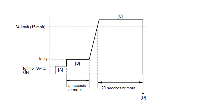
- Connect the Techstream to the DLC3.
- Turn the ignition switch to ON and turn the Techstream on.
-
Clear DTCs (even if no DTCs are stored, perform the clear DTC procedure) (See page
![2016 MY Sienna [12/2015 - 08/2016]; 2GR-FE (ENGINE CONTROL): SFI SYSTEM: DTC CHECK / CLEAR](/t3Portal/stylegraphics/info.gif) ).
).
- Turn the ignition switch off and wait for at least 30 seconds.
- Turn the ignition switch to ON and turn the Techstream on [A].
- Idle the engine for 5 minutes or more [B].
-
Drive the vehicle at 24 km/h (15 mph) or more for 20 seconds or more [C].
CAUTION:
When performing the confirmation driving pattern, obey all speed limits and traffic laws.
- Enter the following menus: Powertrain / Engine / Trouble Codes [D].
-
Read pending DTCs.
HINT:
- If a pending DTC is output, the system is malfunctioning.
- If a pending DTC is not output, perform the following procedure.
- Enter the following menus: Powertrain / Engine / Utility / All Readiness.
- Input the DTC: P0617.
-
Check the DTC judgment result.
Techstream Display
Description
NORMAL
- DTC judgment completed
- System normal
ABNORMAL
- DTC judgment completed
- System abnormal
INCOMPLETE
- DTC judgment not completed
- Perform driving pattern after confirming DTC enabling conditions
N/A
- Unable to perform DTC judgment
- Number of DTCs which do not fulfill DTC preconditions has reached ECU's memory limit
HINT:
- If the judgment result shows NORMAL, the system is normal.
- If the judgment result shows ABNORMAL, the system has a malfunction.
-
If the test result is INCOMPLETE or N/A and no pending DTC is output, perform a universal trip and check for permanent DTCs (See page
).
HINT:
- If a permanent DTC is output, the system is malfunctioning.
- If no permanent DTC is output, the system is normal.
WIRING DIAGRAM
CAUTION / NOTICE / HINT
NOTICE:
Inspect the fuses for circuits related to this system before performing the following inspection procedure.
HINT:
-
The following troubleshooting procedure is based on the premise that the engine is cranked normally.
If the engine does not crank, proceed to the Problem Symptoms Table (See page
). - Read freeze frame data using the Techstream. The ECM records vehicle and driving condition information as freeze frame data the moment a DTC is stored. When troubleshooting, freeze frame data can help determine if the vehicle was moving or stationary, if the engine was warmed up or not, if the air fuel ratio was lean or rich, and other data from the time the malfunction occurred.
PROCEDURE
|
1. |
READ VALUE USING TECHSTREAM (STARTER SIGNAL) |
(a) Connect the Techstream to the DLC3.
(b) Turn the ignition switch to ON.
(c) Turn the Techstream on.
(d) Enter the following menus: Powertrain / Engine / Data List / Starter Signal.
(e) Read the value displayed on the Techstream when the ignition switch is turned ON and the engine is started.
OK:
|
Condition |
Techstream Display |
|---|---|
|
Ignition switch ON |
OFF |
|
Engine start |
ON |
| OK |

|
|

|
2. |
READ VALUE USING TECHSTREAM (STARTER SIGNAL) |
(a) Disconnect the park/neutral position switch connector.
(b) Connect the Techstream to the DLC3.
(c) Turn the ignition switch to ON.
(d) Turn the Techstream on.
(e) Enter the following menus: Powertrain / Engine / Data List / Starter Signal.
(f) Read the value displayed on the Techstream when the ignition switch is turned ON and the engine is started.
Result
|
Result |
Proceed to |
|---|---|
|
OFF |
A |
|
Remains ON (w/ Smart Key System) |
B |
|
Remains ON (w/o Smart Key System) |
C |
| B |
|
| C |
|
|
|
3. |
INSPECT PARK/NEUTRAL POSITION SWITCH |
|
(a) Disconnect the park/neutral position switch connector. |
|
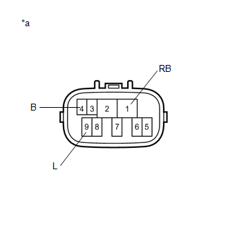
(b) Measure the resistance according to the value(s) in the table below.
Standard Resistance:
|
Tester Connection |
Condition |
Specified Condition |
|---|---|---|
|
4 (B) - 9 (L) |
Shift lever in any position other than P or N |
10 kΩ or higher |
|
1 (RB) - 9 (L) |
Always |
10 kΩ or higher |
Result
|
Result |
Proceed to |
|---|---|
|
Short between 4(B) and 9(L) |
A |
|
Short between 1(RB) and 9(L) |
B |
|
Within standard range (w/ Smart Key System) |
C |
|
Within standard range (w/o Smart Key System) |
D |
Text in Illustration
|
*a |
Component without harness connected (Park/Neutral Position Switch) |
| B |
|
REPLACE PARK/NEUTRAL POSITION SWITCH |
| C |
|
| D |
|
|
|
4. |
REPLACE PARK/NEUTRAL POSITION SWITCH |
(a) Replace the park/neutral position switch.
Result
|
Result |
Proceed to |
|---|---|
|
w/ Smart Key System |
A |
|
w/o Smart Key System |
B |
| B |
|
|
|
5. |
INSPECT ECM (NSW VOLTAGE) |
(a) Disconnect the park/neutral position switch connector.
(b) Disconnect the ECM connector.
|
(c) Measure the voltage according to the value(s) in the table below. Result
|
|
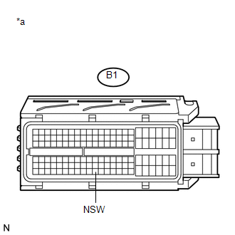
Text in Illustration
|
*a |
Front view of wire harness connector (to ECM) |
| B |
|
|
|
6. |
CHECK HARNESS AND CONNECTOR (POWER MANAGEMENT CONTROL ECU - PARK/NEUTRAL POSITION SWITCH - ECM) |
(a) Disconnect the power management control ECU connector.
(b) Disconnect the park/neutral position switch connector.
(c) Disconnect the ECM connector.
(d) Measure the resistance according to the value(s) in the table below.
Standard Resistance (Check for Open):
|
Tester Connection |
Condition |
Specified Condition |
|---|---|---|
|
A35-3 (STAR) - B1-120 (NSW) |
Always |
Below 1 Ω |
|
B3-4 (B) - B1-120 (NSW) |
Always |
Below 1 Ω |
Standard Resistance (Check for Short):
|
Tester Connection |
Condition |
Specified Condition |
|---|---|---|
|
A35-3 (STAR) or B1-120 (NSW) - Body ground |
Always |
10 Ω or higher |
|
B3-4 (B) or B1-120 (NSW) - Body ground |
Always |
10 Ω or higher |
| OK |
|
| NG |
|
REPAIR OR REPLACE HARNESS OR CONNECTOR |
|
7. |
INSPECT ECM (STA VOLTAGE) |
(a) Disconnect the park/neutral position switch connector.
(b) Disconnect the ECM connector.
|
(c) Measure the voltage according to the value(s) in the table below. Result
|
|
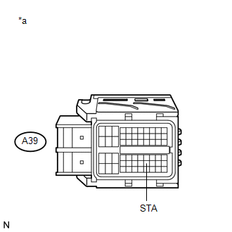
Text in Illustration
|
*a |
Front view of wire harness connector (to ECM) |
| B |
|
|
|
8. |
CHECK HARNESS AND CONNECTOR (POWER MANAGEMENT CONTROL ECU - PARK/NEUTRAL POSITION SWITCH - ST RELAY - ECM |
(a) Remove the ST relay.
(b) Disconnect the power management control ECU connector.
(c) Disconnect the park/neutral position switch connector.
(d) Disconnect the ECM connector.
(e) Measure the resistance according to the value(s) in the table below.
Standard Resistance (Check for Open):
|
Tester Connection |
Condition |
Specified Condition |
|---|---|---|
|
A35-2 (STA) - A39-46 (STA) |
Always |
Below 1 Ω |
|
B3-9 (L) - A39-46 (STA) |
Always |
Below 1 Ω |
|
2 (ST relay holder) - A39-46 (STA) |
Always |
Below 1 Ω |
Standard Resistance (Check for Short):
|
Tester Connection |
Condition |
Specified Condition |
|---|---|---|
|
A35-2 (STA) or A39-46 (STA) - Body ground |
Always |
10 Ω or higher |
|
B3-9 (L) or A39-46 (STA) - Body ground |
Always |
10 Ω or higher |
|
2 (ST relay holder) or A39-46 (STA) - Body ground |
Always |
10 Ω or higher |
| OK |
|
| NG |
|
REPAIR OR REPLACE HARNESS OR CONNECTOR |
|
9. |
INSPECT IGNITION SWITCH ASSEMBLY |
(a) Inspect the ignition switch assembly (See page
).
| NG |
|
|
|
10. |
INSPECT ECM (NSW VOLTAGE) |
(a) Disconnect the park/neutral position switch connector.
(b) Disconnect the ECM connector.
|
(c) Measure the voltage according to the value(s) in the table below. Result
|
|
Text in Illustration
|
*a |
Front view of wire harness connector (to ECM) |
| A |
|
REPAIR OR REPLACE HARNESS OR CONNECTOR (IGNITION SWITCH - PARK/NEUTRAL POSITION SWITCH - ECM) |
| B |
|
|
11. |
INSPECT ECM (STA VOLTAGE) |
(a) Disconnect the park/neutral position switch connector.
(b) Disconnect the ECM connector.
|
(c) Measure the voltage according to the value(s) in the table below. Result
|
|
Text in Illustration
|
*a |
Front view of wire harness connector (to ECM) |
| A |
|
REPAIR OR REPLACE HARNESS OR CONNECTOR (PARK/NEUTRAL POSITION SWITCH - ST RELAY - ECM) |
| B |
|
|
|
|