- Valve timing
- Camshaft timing oil control valve assembly (for intake side of bank 1, 2)
- Oil control valve filter
- Oil pipe
- Camshaft timing gear assembly
- ECM
| Last Modified: 08-28-2024 | 6.11:8.1.0 | Doc ID: RM100000000VIAG |
| Model Year Start: 2016 | Model: Sienna | Prod Date Range: [12/2015 - 08/2016] |
| Title: 2GR-FE (ENGINE CONTROL): SFI SYSTEM: P0011,P0012,P0021,P0022; Camshaft Position "A" - Timing Over-Advanced or System Performance (Bank 1); 2016 MY Sienna [12/2015 - 08/2016] | ||
|
DTC |
P0011 |
Camshaft Position "A" - Timing Over-Advanced or System Performance (Bank 1) |
|
DTC |
P0012 |
Camshaft Position "A" - Timing Over-Retarded (Bank 1) |
|
DTC |
P0021 |
Camshaft Position "A" - Timing Over-Advanced or System Performance (Bank 2) |
|
DTC |
P0022 |
Camshaft Position "A" - Timing Over-Retarded (Bank 2) |
DESCRIPTION
Refer to DTC P0010 (See page
![2016 MY Sienna [12/2015 - 08/2016]; 2GR-FE (ENGINE CONTROL): SFI SYSTEM: P0010,P0020; Camshaft Position "A" Actuator Circuit (Bank 1)+](/t3Portal/stylegraphics/info.gif) ).
).
|
DTC No. |
DTC Detection Condition |
Trouble Area |
|---|---|---|
|
P0011 P0021 |
Intake valve timing is stuck at a certain value when in the advance range (1 trip detection logic) |
|
|
P0012 P0022 |
Intake valve timing is stuck at a certain value when in the retard range (2 trip detection logic) |
|
MONITOR DESCRIPTION
- The ECM optimizes the intake valve timing using the Variable Valve Timing (VVT) system to control the intake camshaft. The VVT system includes the ECM, the camshaft timing oil control valve assembly (for intake side) and the camshaft timing gear assembly.
- The ECM sends a target duty-cycle control signal to the camshaft timing oil control valve assembly (for intake side). This control signal regulates the oil pressure supplied to the camshaft timing gear assembly. The camshaft timing gear assembly can advance or retard the intake camshaft.
- If the difference between the target and actual intake valve timing is large, and changes in the actual intake valve timing are small, the ECM interprets this as the camshaft timing gear assembly stuck malfunction and stores a DTC.
- Example:
-
A DTC is stored when the following conditions "A" and "B" are met:
- It takes 5 seconds or more to change the valve timing by 5°CA (Condition "A").
- After the above condition is met, the camshaft timing oil control valve assembly is forcibly activated 10 seconds (Condition "B").
- DTCs P0011 and P0021 (advanced camshaft timing) are subject to 1 trip detection logic.
- DTCs P0012 and P0022 (retarded camshaft timing) are subject to 2 trip detection logic.
- These DTCs indicate that the camshaft timing gear assembly cannot operate properly due to camshaft timing oil control valve assembly (for intake side) malfunctions or the presence of foreign objects in the camshaft timing oil control valve assembly (for intake side).
MONITOR STRATEGY
|
Related DTCs |
P0011: Advanced camshaft timing (bank 1) P0012: Retarded camshaft timing (bank 1) P0021: Advanced camshaft timing (bank 2) P0022: Retarded camshaft timing (bank 2) |
|
Required Sensors/Components (Main) |
Camshaft timing oil control valve assembly (for intake side) Camshaft timing gear assembly |
|
Required Sensors/Components (Related) |
Crankshaft position sensor, VVT sensor and engine coolant temperature sensor |
|
Frequency of Operation |
Continuous |
|
Duration |
Less than 10 seconds |
|
MIL Operation |
Advanced camshaft timing: Immediately Retarded camshaft timing: 2 driving cycles |
|
Sequence of Operation |
None |
TYPICAL ENABLING CONDITIONS
|
Monitor runs whenever following DTCs are not present |
P0010, P0020 (Camshaft timing oil control valve bank 1, 2) P0016, P0018 (VVT system bank 1, 2 - misalignment) P0102, P0103 (Mass air flow meter) P0115, P0117, P0118 (Engine coolant temperature sensor) P0125 (Insufficient engine coolant temperature for closed loop control) P0335 (Crankshaft position sensor) P0340 (VVT sensor) |
|
Battery voltage |
11 V or higher |
|
Engine speed |
500 to 4000 rpm |
|
Engine coolant temperature |
75 to 100°C (167 to 212°F) |
TYPICAL MALFUNCTION THRESHOLDS
Advanced Camshaft Timing
|
All of the following conditions are met: |
- |
|
Deviation of actual valve timing and target valve timing |
More than 5°CA (Crankshaft Angle) for 5 seconds or more after the VVT hold duty ratio learned value reaches the upper or lower limit. |
|
Valve timing |
No change at advanced valve timing |
Retarded Camshaft Timing
|
All of the following conditions are met: |
- |
|
Deviation of actual valve timing and target valve timing |
More than 5°CA (Crankshaft Angle) for 5 seconds or more after the VVT hold duty ratio learned value reaches the upper or lower limit. |
|
Valve timing |
No change at retarded valve timing |
MONITOR RESULT
Refer to the Checking Monitor Status (See page
).
CONFIRMATION DRIVING PATTERN
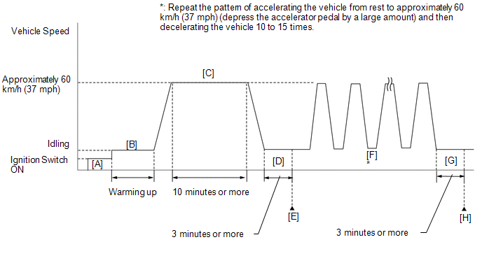
- Connect the Techstream to the DLC3.
- Turn the ignition switch to ON and turn the Techstream on.
-
Clear DTCs (even if no DTCs are stored, perform the clear DTC procedure) (See page
).
- Turn the ignition switch off and wait for at least 30 seconds.
- Turn the ignition switch to ON and turn the Techstream on [A].
- Start the engine and warm it up until the engine coolant temperature reaches 75°C (167°F) or more [B].
-
Drive the vehicle at approximately 60 km/h (37 mph) for 10 minutes or more [C].
CAUTION:
When performing the confirmation driving pattern, obey all speed limits and traffic laws.
- Idle the engine for 3 minutes or more [D].
- Enter the following menus: Powertrain / Engine / Trouble Codes.
-
Read pending DTCs.
HINT:
- If a pending DTC is output, the system is malfunctioning.
- If a pending DTC is not output, perform the following procedure.
- Enter the following menus: Powertrain / Engine / Utility / All Readiness.
- Input the DTC: P0011, P0012, P0021 or P0022.
-
Check the DTC judgment result [E].
Techstream Display
Description
NORMAL
- DTC judgment completed
- System normal
ABNORMAL
- DTC judgment completed
- System abnormal
INCOMPLETE
- DTC judgment not completed
- Perform driving pattern after confirming DTC enabling conditions
N/A
- Unable to perform DTC judgment
- Number of DTCs which do not fulfill DTC preconditions has reached ECU's memory limit
HINT:
- If the judgment result shows NORMAL, the system is normal.
- If the judgment result shows ABNORMAL, the system has a malfunction.
- If the judgment result shows INCOMPLETE or N/A, perform steps [F] through [H].
-
Repeat the pattern of accelerating the vehicle from rest to approximately 60 km/h (37 mph) and then decelerating the vehicle 10 to 15 times [F].
CAUTION:
When performing the confirmation driving pattern, obey all speed limits and traffic laws.
HINT:
Depress the accelerator pedal by a large amount.
- Idle the engine for 3 minutes or more [G].
- Enter the following menus: Powertrain / Engine / Trouble Codes [H].
-
Read Pending DTCs.
HINT:
- If a pending DTC is output, the system is malfunctioning.
- If a pending DTC is not output, perform the following procedure.
-
Check the DTC judgment result again.
HINT:
- If the judgment result shows NORMAL, the system is normal.
- If the judgment result shows ABNORMAL, the system has a malfunction.
- If the judgment result shows INCOMPLETE or N/A, perform the following procedure.
-
Perform universal trip and check for permanent DTCs (See page
).
HINT:
- If a permanent DTC is output, the system is malfunctioning.
- If permanent DTC is not output, the system is normal.
WIRING DIAGRAM
Refer to DTC P0010 (See page
).
CAUTION / NOTICE / HINT
|
Abnormal Bank |
Timing Over Advanced (Valve timing is out of specified range) |
Timing Over Retarded (Valve timing is out of specified range) |
|---|---|---|
|
Bank 1 |
P0011 |
P0012 |
|
Bank 2 |
P0021 |
P0022 |
- If DTC P0011 or P0012 is output, check the VVT system (for intake camshaft of bank 1) circuit.
- If DTC P0021 or P0022 is output, check the VVT system (for intake camshaft of bank 2) circuit.
-
Bank 1 refers to the bank that includes the No. 1 cylinder*.
*: The No. 1 cylinder is the cylinder which is farthest from the transaxle.
- Bank 2 refers to the bank that does not include the No. 1 cylinder.
- DTC P0011, P0012, P0021 or P0022 may be stored when foreign objects in the engine oil are caught in some parts of the system. The DTC will remain stored even if the system returns to normal after a short time. Those foreign objects may then be captured by the oil filter.
- Read freeze frame data using the Techstream. The ECM records vehicle and driving condition information as freeze frame data the moment a DTC is stored. When troubleshooting, freeze frame data can help determine if the vehicle was moving or stationary, if the engine was warmed up or not, if the air fuel ratio was lean or rich, and other data from the time the malfunction occurred.
PROCEDURE
|
1. |
CHECK ANY OTHER DTCS OUTPUT (IN ADDITION TO DTC P0011, P0012, P0021 OR P0022) |
(a) Connect the Techstream to the DLC3.
(b) Turn the ignition switch to ON.
(c) Turn the Techstream on.
(d) Enter the following menus: Powertrain / Engine / Trouble Codes.
(e) Read DTCs.
Result
|
Result |
Proceed to |
|---|---|
|
DTC P0011, P0012, P0021 or P0022 is output |
A |
|
DTC P0011, P0012, P0021 or P0022 and other DTCs are output |
B |
HINT:
If any DTCs other than P0011, P0012, P0021 or P0022 are output, troubleshoot those DTCs first.
| B |

|
|

|
2. |
PERFORM ACTIVE TEST USING TECHSTREAM (CONTROL THE VVT LINEAR (BANK 1 OR 2)) |
(a) Connect the Techstream to the DLC3.
(b) Start the engine.
(c) Turn the Techstream on.
(d) Enter the following menus: Powertrain / Engine / Active Test / Control the VVT Linear (Bank 1) or Control the VVT Linear (Bank 2).
(e) Check the engine speed while operating the camshaft timing oil control valve assembly (for intake camshaft) using the Techstream.
OK
|
Techstream Operation |
Engine Condition |
|---|---|
|
0% |
Normal engine speed |
|
100% |
Engine idles roughly or stalls |
HINT:
Refer to "Data List / Active Test" [VVT OCV Duty #1, VVT Change Angle #1, VVT OCV Duty #2 and VVT Change Angle #2] (See page
).
| NG |
|
|
|
3. |
CHECK WHETHER DTC OUTPUT RECURS (DTC P0011, P0012, P0021 OR P0022) |
(a) Connect the Techstream to the DLC3.
(b) Turn the ignition switch to ON.
(c) Turn the Techstream on.
(d) Clear DTCs (See page
).
(e) Turn the ignition switch off and wait for at least 30 seconds.
(f) Turn the ignition switch to ON and turn the Techstream on.
(g) Start the engine and warm it up.
(h) Drive the vehicle in accordance with the driving pattern described in the Confirmation Driving Pattern.
(i) Enter the following menus: Powertrain / Engine / Utility / All Readiness.
(j) Input the DTC: P0011, P0012, P0021 or P0022.
(k) Check the DTC judgment result.
Result
|
Result |
Proceed to |
|---|---|
|
NORMAL (DTC is not output) |
A |
|
ABNORMAL (DTC P0011, P0012, P0021 or P0022 is output) |
B |
| A |
|
|
|
4. |
CHECK VALVE TIMING (CHECK FOR LOOSE OR JUMPED TEETH ON TIMING CHAIN) |
|
(a) Remove the cylinder head cover sub-assemblies RH and LH. |
|
(b) Turn the crankshaft to align the timing marks of the crankshaft.
(c) Align the notch of the crankshaft pulley to the "0" position.
(d) Check if the timing marks of the camshaft pulley and camshaft bearing cap align.
Text in Illustration
|
*a |
Timing Mark |
(e) Turn the crankshaft clockwise 360° if the timing marks do not align. Check if they align once again.
OK:
The timing marks of the camshaft pulley and the camshaft bearing cap align when the notch of the crankshaft pulley is in the "0" position.
| NG |
|
|
|
5. |
INSPECT CAMSHAFT TIMING OIL CONTROL VALVE ASSEMBLY (FOR INTAKE SIDE) |
(a) Inspect the camshaft timing oil control valve assembly (for intake side) (See page
).
| NG |
|
REPLACE CAMSHAFT TIMING OIL CONTROL VALVE ASSEMBLY (FOR INTAKE SIDE) |
|
|
6. |
INSPECT OIL CONTROL VALVE FILTER AND OIL PIPE |
|
(a) Remove the No. 1 oil pipe or No. 2 oil pipe. Text in Illustration
|
|
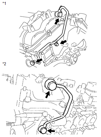
(b) Remove the oil control valve filter RH or oil control valve filter LH.
(c) Check that the oil control valve filter and oil pipe are not clogged.
OK:
The oil control valve filter and oil pipe are not clogged.
| NG |
|
|
|
7. |
REPLACE CAMSHAFT TIMING GEAR ASSEMBLY (BANK 1 OR 2) |
(a) Replace the camshaft timing gear assembly (bank 1 or bank 2) (See page
).
HINT:
Perform "Inspection After Repair" after replacing the camshaft timing gear assembly (See page
).
|
|
8. |
CHECK WHETHER DTC OUTPUT RECURS |
(a) Connect the Techstream to the DLC3.
(b) Turn the ignition switch to ON.
(c) Turn the Techstream on.
(d) Clear DTCs (See page
).
(e) Turn the ignition switch off and wait for at least 30 seconds.
(f) Turn the ignition switch to ON and turn the Techstream on.
(g) Start the engine and warm it up.
(h) Drive the vehicle in accordance with the driving pattern described in the Confirmation Driving Pattern.
(i) Enter the following menus: Powertrain / Engine / Utility / All Readiness.
(j) Input the DTC: P0011, P0012, P0021 or P0022.
(k) Check the DTC judgment result.
Result
|
Result |
Proceed to |
|---|---|
|
NORMAL (DTC is not output) |
A |
|
ABNORMAL (DTC P0011, P0012, P0021 or P0022 is output) |
B |
HINT:
DTC P0011, P0012, P0021 or P0022 is output when foreign objects in engine oil are caught in some parts of the system. These codes will remain stored even if the system returns to normal after a short time. These foreign objects may then be captured by the oil filter, thus eliminating the source of the problem.
| A |
|
END |
| B |
|
|
|
|