| Last Modified: 08-28-2024 | 6.11:8.1.0 | Doc ID: RM100000000VIA7 |
| Model Year Start: 2016 | Model: Sienna | Prod Date Range: [12/2015 - 08/2016] |
| Title: 2GR-FE (ENGINE CONTROL): SFI SYSTEM: ACIS Control Circuit; 2016 MY Sienna [12/2015 - 08/2016] | ||
|
ACIS Control Circuit |
DESCRIPTION
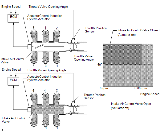
This circuit opens and closes the intake air control valve (intake air surge tank assembly) in response to changes in the engine load in order to increase the intake efficiency using the acoustic control induction system.
When the engine speed is between 0 and 4300 rpm and the throttle valve opening angle is 60° or more, the ECM supplies current to the actuator (on status), to close the intake air control valve. Under other conditions, the VSV is usually off and the intake air control valve is open.
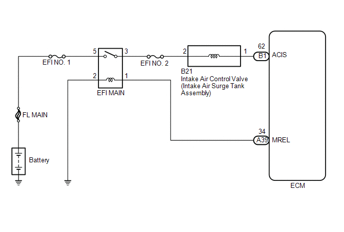
WIRING DIAGRAM
CAUTION / NOTICE / HINT
NOTICE:
Inspect the fuses for circuits related to this system before performing the following inspection procedure.
PROCEDURE
|
1. |
PERFORM ACTIVE TEST USING TECHSTREAM (ACTIVATE THE VSV FOR INTAKE CONTROL) |
(a) Connect the Techstream to the DLC3.
(b) Turn the ignition switch to ON.
(c) Turn the Techstream on.
(d) Enter the following menus: Powertrain / Engine / Active Test / Activate the VSV for Intake Control.
(e) Check if operating noise can be heard when operating the intake air control valve (intake air surge tank assembly) using the Techstream.
OK:
Operating noise can be heard.
| OK |

|
PROCEED TO NEXT SUSPECTED AREA SHOWN IN PROBLEM SYMPTOMS TABLE |
|

|
2. |
CHECK INTAKE AIR SURGE TANK (INTAKE AIR SURGE TANK ASSEMBLY) (VALVE OPERATION) |
|
(a) Disconnect the intake air control valve (intake air surge tank assembly) connector. |
|
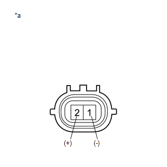
(b) Apply battery voltage between the terminals of the intake air control valve connector.
Text in Illustration
|
*a |
Component without harness connected (Intake Air Control Valve (Intake Air Surge Tank Assembly)) |
(c) Check the intake air control valve (intake air surge tank assembly) operation.
OK:
Operating noise can be heard.
| NG |
|
|
|
3. |
CHECK TERMINAL VOLTAGE (INTAKE AIR CONTROL VALVE (INTAKE AIR SURGE TANK ASSEMBLY) POWER SOURCE) |
|
(a) Disconnect the intake air control valve (intake air surge tank assembly) connector. |
|
(b) Turn the ignition switch to ON.
(c) Measure the voltage according to the value(s) in the table below.
Standard Voltage:
|
Tester Connection |
Switch Condition |
Specified Condition |
|---|---|---|
|
B21-2 - Body ground |
Ignition switch ON |
11 to 14 V |
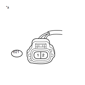
Text in Illustration
|
*a |
Front view of wire harness connector (to Intake Air Control Valve (Intake Air Surge Tank Assembly)) |
| NG |
|
REPAIR OR REPLACE HARNESS OR CONNECTOR (EFI NO. 2 FUSE - INTAKE AIR CONTROL VALVE (INTAKE AIR SURGE TANK ASSEMBLY)) |
|
|
4. |
CHECK HARNESS AND CONNECTOR (INTAKE AIR CONTROL VALVE (INTAKE AIR SURGE TANK ASSEMBLY) - ECM) |
(a) Disconnect the intake air control valve (intake air surge tank assembly) connector.
(b) Disconnect the ECM connector.
(c) Measure the resistance according to the value(s) in the table below.
Standard Resistance (Check for Open):
|
Tester Connection |
Condition |
Specified Condition |
|---|---|---|
|
B21-1 - B1-62 (ACIS) |
Always |
Below 1 Ω |
Standard Resistance (Check for Short):
|
Tester Connection |
Condition |
Specified Condition |
|---|---|---|
|
B21-1 or B1-62 (ACIS) - Body ground |
Always |
10 kΩ or higher |
| OK |
|
| NG |
|
REPAIR OR REPLACE HARNESS OR CONNECTOR |
|
|
|