| Last Modified: 08-28-2024 | 6.11:8.1.0 | Doc ID: RM100000000VI9Y |
| Model Year Start: 2016 | Model: Sienna | Prod Date Range: [12/2015 - 08/2016] |
| Title: 2GR-FE (ENGINE CONTROL): SFI SYSTEM: Starter Signal Circuit; 2016 MY Sienna [12/2015 - 08/2016] | ||
|
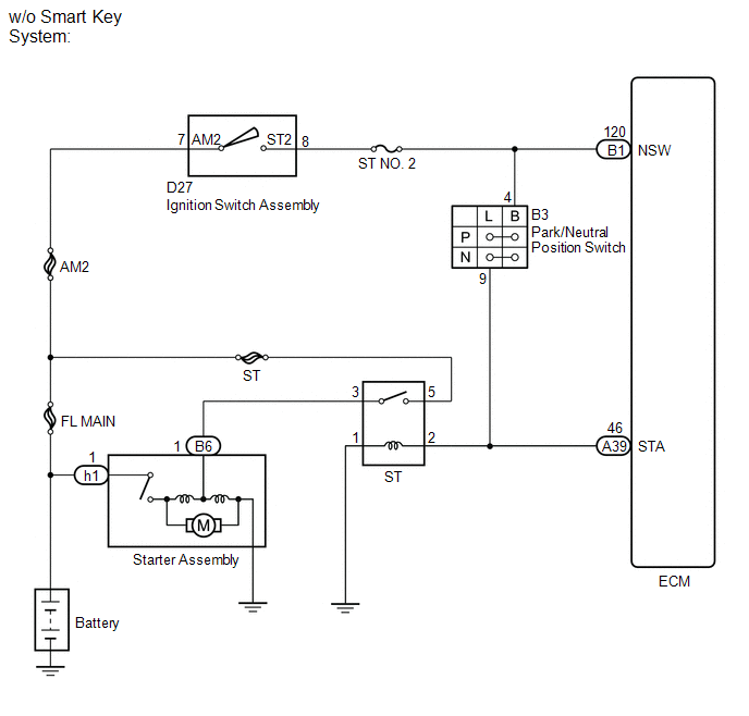
Starter Signal Circuit |
DESCRIPTION
While the engine is being cranked, current flows from terminal ST2 of the ignition switch to the park/neutral position switch and also flows to terminal STA of the ECM (STA signal).
WIRING DIAGRAM
CAUTION / NOTICE / HINT
NOTICE:
Inspect the fuses for circuits related to this system before performing the following inspection procedure.
PROCEDURE
|
1. |
READ VALUE USING TECHSTREAM (STARTER SIGNAL) |
(a) Connect the Techstream to the DLC3.
(b) Turn the ignition switch to ON.
(c) Turn the Techstream on.
(d) Enter the following menus: Powertrain / Engine / Data List / Starter Signal.
(e) Read the value displayed on the Techstream when the ignition switch is turned ON and the engine is started.
OK:
|
Condition |
Techstream Display |
|---|---|
|
Ignition switch ON |
OFF |
|
Engine started |
ON |
Result
|
Result |
Proceed to |
|---|---|
|
NG |
A |
|
OK |
B |
| B |

|
|

|
2. |
INSPECT PARK/NEUTRAL POSITION SWITCH (B - L) |
(a) Inspect the park/neutral position switch (See page
![2016 MY Sienna [12/2015 - 08/2016]; U660E (AUTOMATIC TRANSMISSION / TRANSAXLE): PARK / NEUTRAL POSITION SWITCH: INSPECTION](/t3Portal/stylegraphics/info.gif) for 2WD,
for AWD).
for 2WD,
for AWD).
Result
|
Result |
Proceed to |
|---|---|
|
OK |
A |
|
NG (for 2WD) |
B |
|
NG (for AWD) |
C |
| B |
|
| C |
|
|
|
3. |
INSPECT IGNITION SWITCH ASSEMBLY (AM2 - ST2) |
(a) Inspect the ignition switch assembly (See page
).
| NG |
|
|
|
4. |
CHECK HARNESS AND CONNECTOR (IGNITION SWITCH ASSEMBLY - PARK/NEUTRAL POSITION SWITCH) |
(a) Disconnect the ignition switch assembly connector.
(b) Disconnect the park/neutral position switch connector.
(c) Measure the resistance according to the value(s) in the table below.
Standard Resistance (Check for Open):
|
Tester Connection |
Condition |
Specified Condition |
|---|---|---|
|
D27-8 (ST2) - B3-4 (B) |
Always |
Below 1 Ω |
Standard Resistance (Check for Short):
|
Tester Connection |
Condition |
Specified Condition |
|---|---|---|
|
D27-8 (ST2) or B3-4 (B) - Body ground |
Always |
10 kΩ or higher |
| NG |
|
REPAIR OR REPLACE HARNESS OR CONNECTOR |
|
|
5. |
CHECK HARNESS AND CONNECTOR (PARK/NEUTRAL POSITION SWITCH - ST RELAY - ECM) |
(a) Remove the ST relay from the engine room relay block.
(b) Disconnect the park/neutral position switch connector.
(c) Disconnect the ECM connector.
(d) Measure the resistance according to the value(s) in the table below.
Standard Resistance (Check for Open):
|
Tester Connection |
Condition |
Specified Condition |
|---|---|---|
|
2 (ST relay holder) - A39-46 (STA) |
Always |
Below 1 Ω |
|
2 (ST relay holder) - B3-9 (L) |
Always |
Below 1 Ω |
Standard Resistance (Check for Open):
|
Tester Connection |
Condition |
Specified Condition |
|---|---|---|
|
2 (ST relay holder) or A39-46 (STA) - body ground |
Always |
10 kΩ or higher |
|
2 (ST relay holder) or B3-9 (L) - body ground |
Always |
10 kΩ or higher |
| NG |
|
REPAIR OR REPLACE HARNESS OR CONNECTOR |
|
|
6. |
INSPECT BATTERY |
(a) Check that the battery is not depleted.
OK:
Battery is not depleted.
| NG |
|
REPLACE BATTERY |
|
|
7. |
CHECK BATTERY TERMINAL |
(a) Check that the battery terminal are not loose or corroded.
OK:
Battery terminals are not loose or corroded.
| OK |
|
REPAIR OR REPLACE STARTER CIRCUIT (STARTER ASSEMBLY - ST RELAY) |
| NG |
|
REPAIR OR REPLACE BATTERY TERMINAL |
|
|
|