| Last Modified: 08-28-2024 | 6.11:8.1.0 | Doc ID: RM100000000VI9X |
| Model Year Start: 2016 | Model: Sienna | Prod Date Range: [12/2015 - 08/2016] |
| Title: 2GR-FE (ENGINE CONTROL): SFI SYSTEM: ECM Power Source Circuit; 2016 MY Sienna [12/2015 - 08/2016] | ||
|
ECM Power Source Circuit |
DESCRIPTION
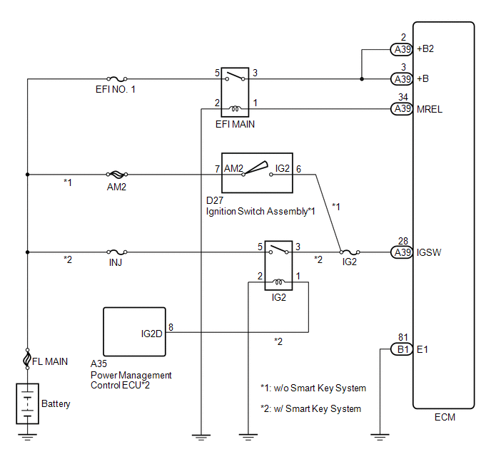
When the ignition switch is turned ON, the battery voltage is applied to IGSW of the ECM. The output signal from the MREL terminal of the ECM causes a current to flow to the coil, closing the contact of the EFI MAIN relay and supplying power to terminals +B and +B2 of the ECM.
WIRING DIAGRAM
CAUTION / NOTICE / HINT
NOTICE:
-
After turning ignition switch off, waiting time may be required before disconnecting the cable from the negative (-) battery terminal. Therefore, make sure to read the disconnecting the cable from the negative (-) battery terminal notices before proceeding with work (See page
![2016 MY Sienna [12/2015 - 08/2016]; INTRODUCTION: REPAIR INSTRUCTION: PRECAUTION](/t3Portal/stylegraphics/info.gif) ).
).
- Inspect the fuses for circuits related to this system before performing the following inspection procedure.
PROCEDURE
|
1. |
CHECK HARNESS AND CONNECTOR (ECM - BODY GROUND) |
(a) Disconnect the ECM connector.
(b) Measure the resistance according to the value(s) in the table below.
Standard Resistance:
|
Tester Connection |
Condition |
Specified Condition |
|---|---|---|
|
B1-81 (E1) - Body ground |
Always |
Below 1 Ω |
| NG |

|
REPAIR OR REPLACE HARNESS OR CONNECTOR |
|

|
2. |
INSPECT ECM (IGSW VOLTAGE) |
|
(a) Disconnect the ECM connector. |
|
(b) Turn the ignition switch to ON.
(c) Measure the voltage according to the value(s) in the table below.
Standard Voltage:
|
Tester Connection |
Switch Condition |
Specified Condition |
|---|---|---|
|
A39-28 (IGSW) - Body ground |
Ignition switch ON |
11 to 14 V |
Result
|
Result |
Proceed to |
|---|---|
|
OK |
A |
|
NG (w/ Smart Key System) |
B |
|
NG (w/o Smart Key System) |
C |
Text in Illustration
|
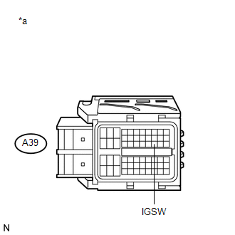
*a |
Front view of wire harness connector (to ECM) |
| B |
|
| C |
|
|
|
3. |
INSPECT ECM (MREL VOLTAGE) |
|
(a) Remove the EFI MAIN relay. |
|
(b) Turn the ignition switch to ON.
(c) Measure the voltage according to the value(s) in the table below.
Standard Voltage:
|
Tester Connection |
Switch Condition |
Specified Condition |
|---|---|---|
|
1 (EFI MAIN relay holder) - Body ground |
Ignition switch ON |
11 to 14 V |
Text in Illustration
|
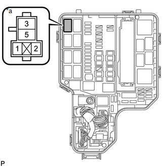
*a |
EFI MAIN relay terminal |
| NG |
|
|
|
4. |
INSPECT EFI MAIN RELAY |
(a) Inspect the EFI MAIN relay (See page
).
| NG |
|
REPLACE EFI MAIN RELAY |
|
|
5. |
CHECK HARNESS AND CONNECTOR (EFI MAIN RELAY) |
(a) Remove the EFI MAIN relay from the engine room relay block.
(b) Remove the A/F HTR relay from the engine room relay block.
HINT:
Remove the A/F HTR relay connected between the checked terminals as the coil inside the relay influences the measurement value.
(c) Disconnect the ECM connector.
(d) Measure the resistance according to the value(s) in the table below.
Standard Resistance (Check for Open):
|
Tester Connection |
Condition |
Specified Condition |
|---|---|---|
|
3 (EFI MAIN relay holder) - A39-3 (+B) |
Always |
Below 1 Ω |
|
3 (EFI MAIN relay holder) - A39-2 (+B2) |
Always |
Below 1 Ω |
Standard Resistance (Check for Short):
|
Tester Connection |
Condition |
Specified Condition |
|---|---|---|
|
3 (EFI MAIN relay holder) or A39-3 (+B) - Body ground |
Always |
10 kΩ or higher |
|
3 (EFI MAIN relay holder) or A39-2 (+B2) - Body ground |
Always |
10 kΩ or higher |
| NG |
|
REPAIR OR REPLACE HARNESS OR CONNECTOR (EFI MAIN RELAY - ECM) |
|
|
6. |
CHECK HARNESS AND CONNECTOR (BATTERY - EFI MAIN RELAY) |
(a) Remove the EFI MAIN relay from the engine room relay block.
(b) Disconnect the cable from the negative (-) battery terminal.
(c) Disconnect the cable from the positive (+) battery terminal.
(d) Measure the resistance according to the value(s) in the table below.
Standard Resistance (Check for Open):
|
Tester Connection |
Condition |
Specified Condition |
|---|---|---|
|
5 (EFI MAIN relay holder) - Battery positive (+) terminal |
Always |
Below 1 Ω |
Standard Resistance (Check for Short):
|
Tester Connection |
Condition |
Specified Condition |
|---|---|---|
|
5 (EFI MAIN relay holder) - Body ground |
Always |
10 kΩ or higher |
| NG |
|
REPAIR OR REPLACE HARNESS OR CONNECTOR |
|
|
7. |
CHECK HARNESS AND CONNECTOR (EFI MAIN RELAY - BODY GROUND) |
(a) Remove the EFI MAIN relay from the engine room relay block.
(b) Measure the resistance according to the value(s) in the table below.
Standard Resistance (Check for Open):
|
Tester Connection |
Condition |
Specified Condition |
|---|---|---|
|
2 (EFI MAIN relay holder) - Body ground |
Always |
Below 1 Ω |
| OK |
|
PROCEED TO NEXT SUSPECTED AREA SHOWN IN PROBLEM SYMPTOMS TABLE |
| NG |
|
REPAIR OR REPLACE HARNESS OR CONNECTOR |
|
8. |
CHECK HARNESS AND CONNECTOR (EFI MAIN RELAY TERMINAL - ECM) |
(a) Disconnect the ECM connector.
(b) Remove the EFI MAIN relay from the engine room relay block.
(c) Measure the resistance according to the value(s) in the table below.
Standard Resistance (Check for Open):
|
Tester Connection |
Condition |
Specified Condition |
|---|---|---|
|
A39-34 (MREL) - 1 (EFI MAIN relay holder) |
Always |
Below 1 Ω |
Standard Resistance (Check for Short):
|
Tester Connection |
Condition |
Specified Condition |
|---|---|---|
|
A39-34 (MREL) or 1 (EFI MAIN relay holder) - Body ground |
Always |
10 kΩ or higher |
| OK |
|
| NG |
|
REPAIR OR REPLACE HARNESS OR CONNECTOR (EFI MAIN RELAY - ECM) |
|
9. |
INSPECT IG2 RELAY |
(a) Inspect the IG2 relay (See page
).
| NG |
|
REPLACE IG2 RELAY |
|
|
10. |
CHECK HARNESS AND CONNECTOR (IG2 RELAY - ECM) |
(a) Remove the IG2 relay from the engine room relay block.
(b) Disconnect the ECM connector.
(c) Measure the resistance according to the value(s) in the table below.
Standard Resistance (Check for Open):
|
Tester Connection |
Condition |
Specified Condition |
|---|---|---|
|
3 (IG2 relay holder) - A39-28 (IGSW) |
Always |
Below 1 Ω |
Standard Resistance (Check for Short):
|
Tester Connection |
Condition |
Specified Condition |
|---|---|---|
|
3 (IG2 relay holder) or A39-28 (IGSW) - Body ground |
Always |
10 kΩ or higher |
| NG |
|
REPAIR OR REPLACE HARNESS OR CONNECTOR |
|
|
11. |
CHECK HARNESS AND CONNECTOR (IG2 RELAY POWER SOURCE) |
|
(a) Remove the IG2 relay from the engine room relay block. |
|
(b) Measure the voltage according to the value(s) in the table below.
Standard Voltage:
|
Tester Connection |
Condition |
Specified Condition |
|---|---|---|
|
5 (IG2 relay holder) - Body ground |
Always |
11 to 14 V |
Text in Illustration
|
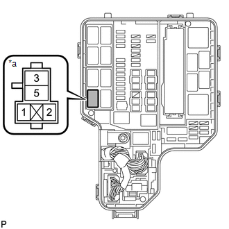
*a |
IG2 relay terminal |
| NG |
|
REPAIR OR REPLACE HARNESS OR CONNECTOR (IG2 RELAY - BATTERY) |
|
|
12. |
CHECK HARNESS AND CONNECTOR (IG2 RELAY - BODY GROUND) |
(a) Remove the IG2 relay from the engine room relay block.
(b) Measure the resistance according to the value(s) in the table below.
Standard Resistance (Check for Open):
|
Tester Connection |
Condition |
Specified Condition |
|---|---|---|
|
2 (IG2 relay holder) - Body ground |
Always |
Below 1 Ω |
| NG |
|
REPAIR OR REPLACE HARNESS OR CONNECTOR |
|
|
13. |
CHECK HARNESS AND CONNECTOR (IG2 RELAY - POWER MANAGEMENT CONTROL ECU) |
(a) Disconnect the power management control ECU connector.
(b) Remove the IG2 relay from the engine room relay block.
(c) Measure the resistance according to the value(s) in the table below.
Standard Resistance (Check for Open):
|
Tester Connection |
Condition |
Specified Condition |
|---|---|---|
|
1 (IG2 relay holder) - A35-8 (IG2D) |
Always |
Below 1 Ω |
Standard Resistance (Check for Short):
|
Tester Connection |
Condition |
Specified Condition |
|---|---|---|
|
1 (IG2 relay holder) - A35-8 (IG2D) - Body ground |
Always |
10 kΩ or higher |
| OK |
|
| NG |
|
REPAIR OR REPLACE HARNESS OR CONNECTOR |
|
14. |
INSPECT IGNITION SWITCH ASSEMBLY |
(a) Inspect the ignition switch assembly (See page
).
| NG |
|
|
|
15. |
CHECK HARNESS AND CONNECTOR (IGNITION SWITCH ASSEMBLY - ECM) |
(a) Disconnect the ignition switch assembly connector.
(b) Disconnect the ECM connector.
(c) Measure the resistance according to the value(s) in the table below.
Standard Resistance (Check for Open):
|
Tester Connection |
Condition |
Specified Condition |
|---|---|---|
|
D27-6 (IG2) - A39-28 (IGSW) |
Always |
Below 1 Ω |
Standard Resistance (Check for Short):
|
Tester Connection |
Condition |
Specified Condition |
|---|---|---|
|
D27-6 (IG2) or A39-28 (IGSW) - Body ground |
Always |
10 kΩ or higher |
| OK |
|
REPAIR OR REPLACE HARNESS OR CONNECTOR (BATTERY - IGNITION SWITCH ASSEMBLY) |
| NG |
|
REPAIR OR REPLACE HARNESS OR CONNECTOR |
|
|
|