| Last Modified: 08-28-2024 | 6.11:8.1.0 | Doc ID: RM100000000VI9L |
| Model Year Start: 2016 | Model: Sienna | Prod Date Range: [12/2015 - 08/2016] |
| Title: 2GR-FE (ENGINE CONTROL): THROTTLE BODY: INSTALLATION; 2016 MY Sienna [12/2015 - 08/2016] | ||
INSTALLATION
PROCEDURE
1. INSTALL THROTTLE WITH MOTOR BODY ASSEMBLY
|
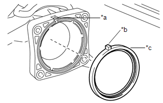
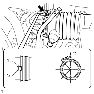
(a) Install a new gasket to the intake air surge tank assembly. Text in Illustration
|
|
(b) Install the throttle body and wire harness clamp stay to the intake air surge tank assembly with the 4 bolts.
Torque:
10 N·m {102 kgf·cm, 7 ft·lbf}
(c) Connect the throttle body connector and wire harness clamp.
2. INSTALL NO. 2 WATER BY-PASS HOSE
|
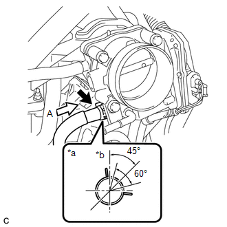
(a) Connect the No. 2 water by-pass hose with the clip. Text in Illustration
HINT: Connect the hose so that the direction of the hose clip is as indicated in the illustration. |
|
3. INSTALL WATER BY-PASS HOSE
|
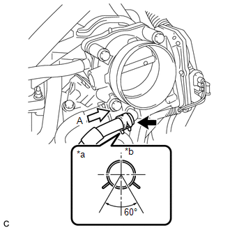
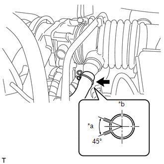
(a) Connect the water by-pass hose with the clip. Text in Illustration
HINT: Connect the hose so that the direction of the hose clip is as indicated in the illustration. |
|
4. INSTALL AIR CLEANER AND HOSE
|
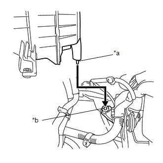
(a) Insert the tab of the air cleaner assembly to the hole of the vehicle body as shown in the illustration. Text in Illustration
|
|
(b) Install the air cleaner assembly with the 2 bolts.
Torque:
5.0 N·m {51 kgf·cm, 44 in·lbf}
|
(c) Connect the air cleaner hose to the throttle body with the hose clamp. Text in Illustration
HINT: Connect the hose so that the direction of the hose clip is as indicated in the illustration. |
|
(d) Install the fuel vapor feed hose to the hose clamp.
|
(e) Connect the No. 2 ventilation hose with the clip. Text in Illustration
HINT: Connect the hose so that the direction of the hose clip is as indicated in the illustration. |
|
(f) Connect the 2 vacuum hoses.
(g) Engage the 2 wire harness clamps.
(h) Connect the vacuum switching valve connector.
(i) Install the vacuum hose to the hose clamp.
(j) Connect the vacuum hose to the intake air surge tank assembly.
(k) Engage the wire harness clamp.
(l) Connect the mass air flow meter connector.
5. INSTALL AIR CLEANER INLET COVER ASSEMBLY SEAL
(a) Install the air cleaner inlet cover assembly seal with the 2 bolts.
Torque:
6.0 N·m {61 kgf·cm, 53 in·lbf}
(b) Engage the 3 vacuum hose clamps to the air cleaner inlet cover assembly seal.
6. ADD ENGINE COOLANT
![2016 MY Sienna [12/2015 - 08/2016]; 2GR-FE COOLING: COOLANT: REPLACEMENT+](/t3Portal/stylegraphics/info.gif)
7. INSPECT FOR COOLANT LEAK
8. INSTALL NO. 1 ENGINE UNDER COVER
9. INSTALL V-BANK COVER SUB-ASSEMBLY
10. INSTALL FRONT OUTER COWL TOP PANEL SUB-ASSEMBLY
11. INSTALL WINDSHIELD WIPER MOTOR AND LINK ASSEMBLY
(See page
)
12. PERFORM INITIALIZATION
NOTICE:
- Be sure to perform this procedure after reassembling the throttle body or removing and reinstalling any throttle body component.
- Perform the following procedure after replacing the ECM, throttle body assembly or any throttle body components. The following procedure should also be performed if the throttle body is cleaned.
- Be sure to perform this procedure after replacing the ECM and reconnecting the battery cable.
(a) Disconnect the cable from the negative (-) battery terminal. Wait at least 60 seconds and reconnect the cable.
(b) Turn the ignition switch to ON without operating the accelerator pedal.
NOTICE:
If the accelerator pedal is operated, perform the above steps again.
(c) Connect the Techstream to the DLC3 and clear the DTCs (See page
).
(d) Start the engine and check that the MIL is not illuminated and that the idle speed is within the specified range when the A/C is switched off after the engine is warmed up.
Standard:
|
Condition |
Engine Idle Speed |
|---|---|
|
A/C switched off |
600 to 700 rpm |
NOTICE:
- Be sure to perform this step with all accessories off.
- Make sure that the shift lever is in neutral.
(e) Enter the following menus: Powertrain/ Engine / Data List/ Throttle Sensor Position. Fully depress the accelerator pedal and check that the value is 60% or more.
(f) Perform a road test and confirm that there are no abnormalities.
|
|
|