 Service Information
- Air Conditioning Compressor and Condenser Hose Seal - Large
- Air Conditioning Compressor and Condenser Hose Seal - Small
- Exhaust Gas Recirculation Coolant Feed Pipe Seal
- Exhaust Gas Recirculation Cooler Pipe Gasket
- Exhaust Gas Recirculation Pipe Gasket[5x]
- Exhaust Gas Recirculation Valve Cooler Bypass Valve Gasket
- Turbocharger Air Inlet Adapter Seal
- Upper Intake Manifold Seal[2x]
Warning: In order to avoid being burned, do not service the exhaust system while it is still hot. Service the system when it is cool.
Warning: Avoid contact with HOT components. Wear safety glasses and protective gloves to avoid personal injury.
- Recover the refrigerant.Refrigerant Recovery and Recharging
- Disconnect the battery negative cable.Battery Negative Cable Disconnection and Connection
- Drain the cooling system.Cooling System Draining and Filling
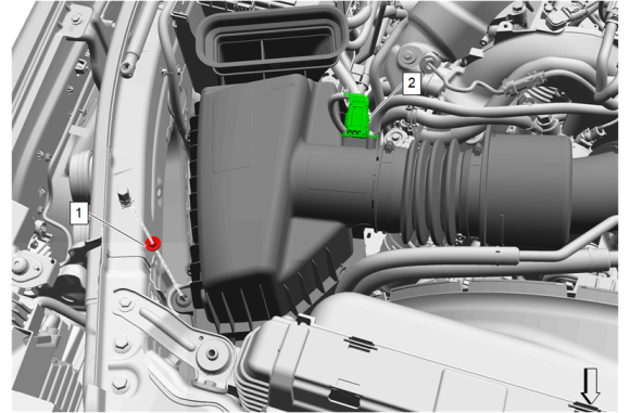
- Electrical Connector(2)»Disconnect
- Air Cleaner Nut(1)»Remove
- Remove wiring harness retainers from air cleaner assembly.
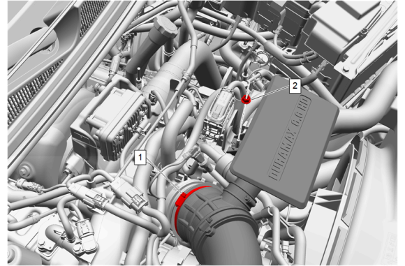
- Turbocharger Outlet Duct Connector Clamp(1)»Loosen
- Air Cleaner Resonator Nut(2)»Remove
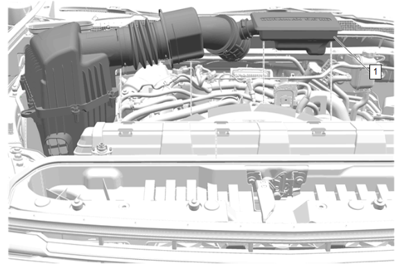
- Remove the air cleaner and air cleaner outlet resonator (1) as an assembly.
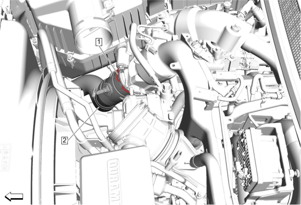
- Disconnect the charge air temperature sensor electrical connector.
- Retainer Spring(1)»Disengage
- Charge Air Cooler Outlet Air Hose(2)@Throttle Body Assembly»Remove and position aside
- Disconnect the throttle body electrical connector.
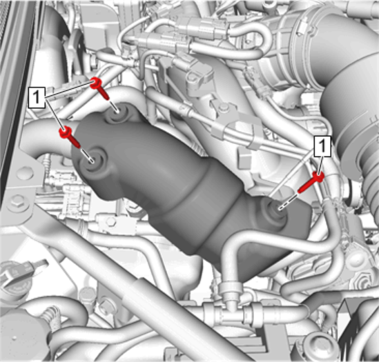
- Exhaust Gas Recirculation Valve Pipe Heat Shield Bolt(1)»Remove[3x]
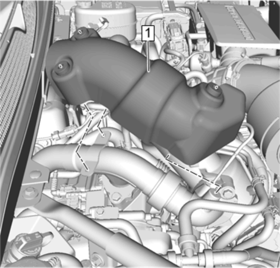
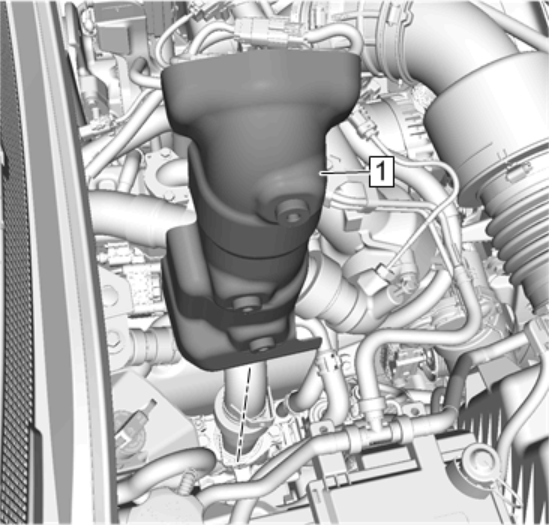
- Exhaust Gas Recirculation Pipe Shield(1)»Remove
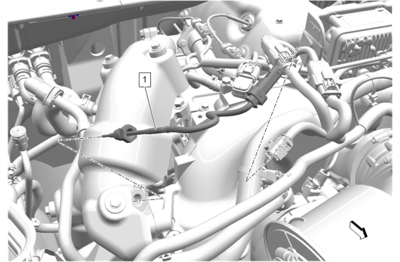
- Disconnect the exhaust gas recirculation cooler temperature sensor (1) electrical connector.
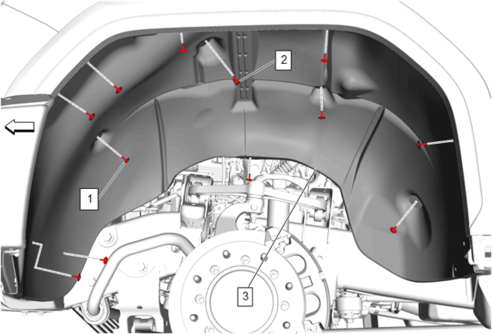
- Front Wheelhouse Liner-Right Side(3)»Remove—Front Wheelhouse Liner Replacement
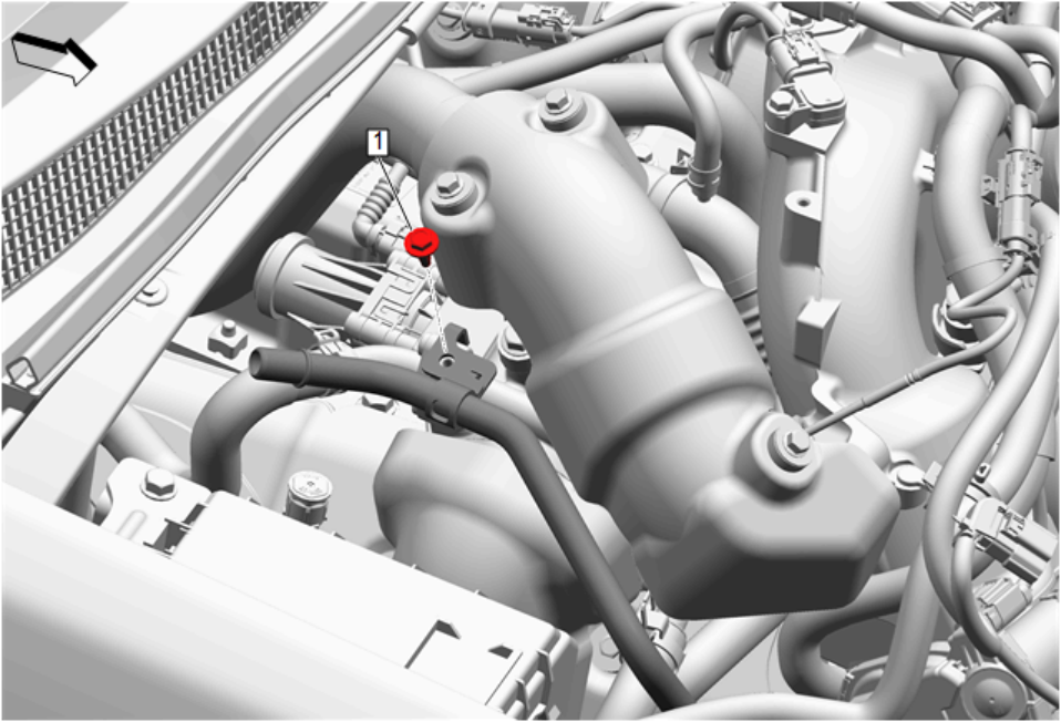
- Exhaust Gas Recirculation Valve Pipe Heat Shield Bolt(1)»Remove[2x]
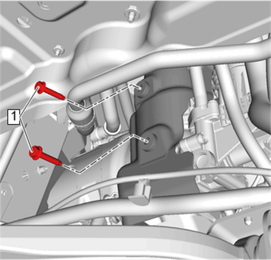
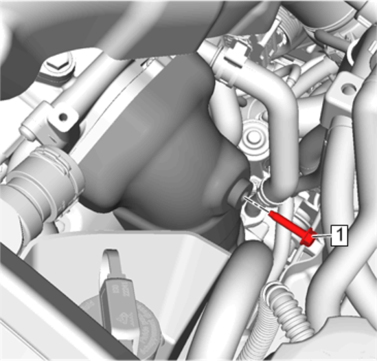
- Radiator Outlet Hose Bracket Bolt(1)»Remove
- Exhaust Gas Recirculation Valve Pipe Heat Shield Bolt(1)»Remove
- Exhaust Gas Recirculation Pipe Shield(1)»Remove
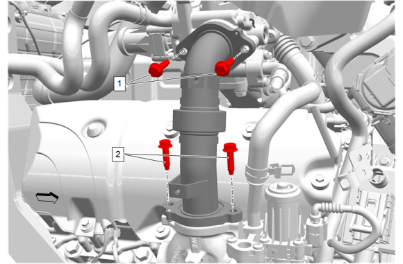
- Exhaust Gas Recirculation Pipe Bolt(1, 2)»Remove[4x]
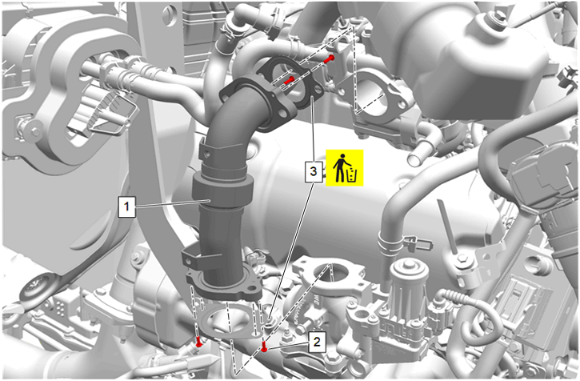
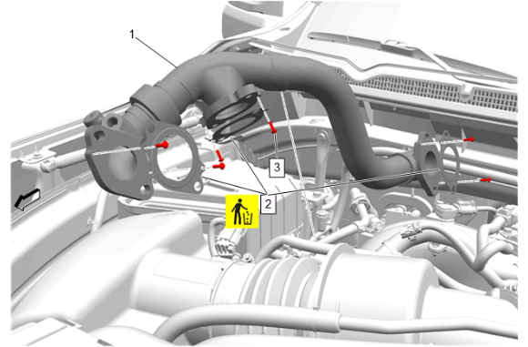
- Exhaust Gas Recirculation Pipe(1)»Remove
- Retainer(2)»Remove[4x]
- Exhaust Gas Recirculation Pipe Gasket(3)»Remove and DISCARD[2x]
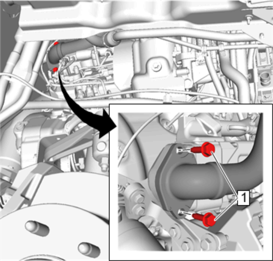
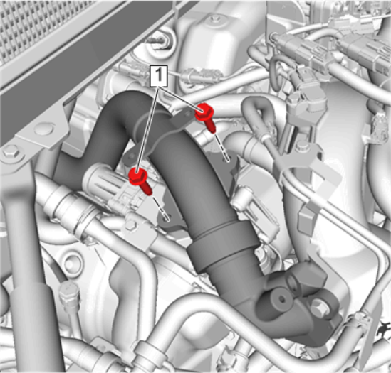
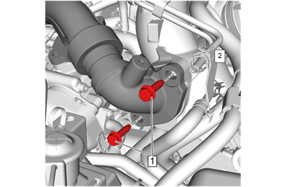
- Exhaust Gas Recirculation Pipe Bolt(1)»Remove[2x]
- Exhaust Gas Recirculation Pipe Bolt(1)»Remove[2x]
- Exhaust Gas Recirculation Pipe Bolt(1)»Remove[2x]
- Exhaust Gas Recirculation Pipe(1)»Remove
- Retainer(3)»Remove[6x]
- Exhaust Gas Recirculation Pipe Gasket(2)»Remove and DISCARD[3x]
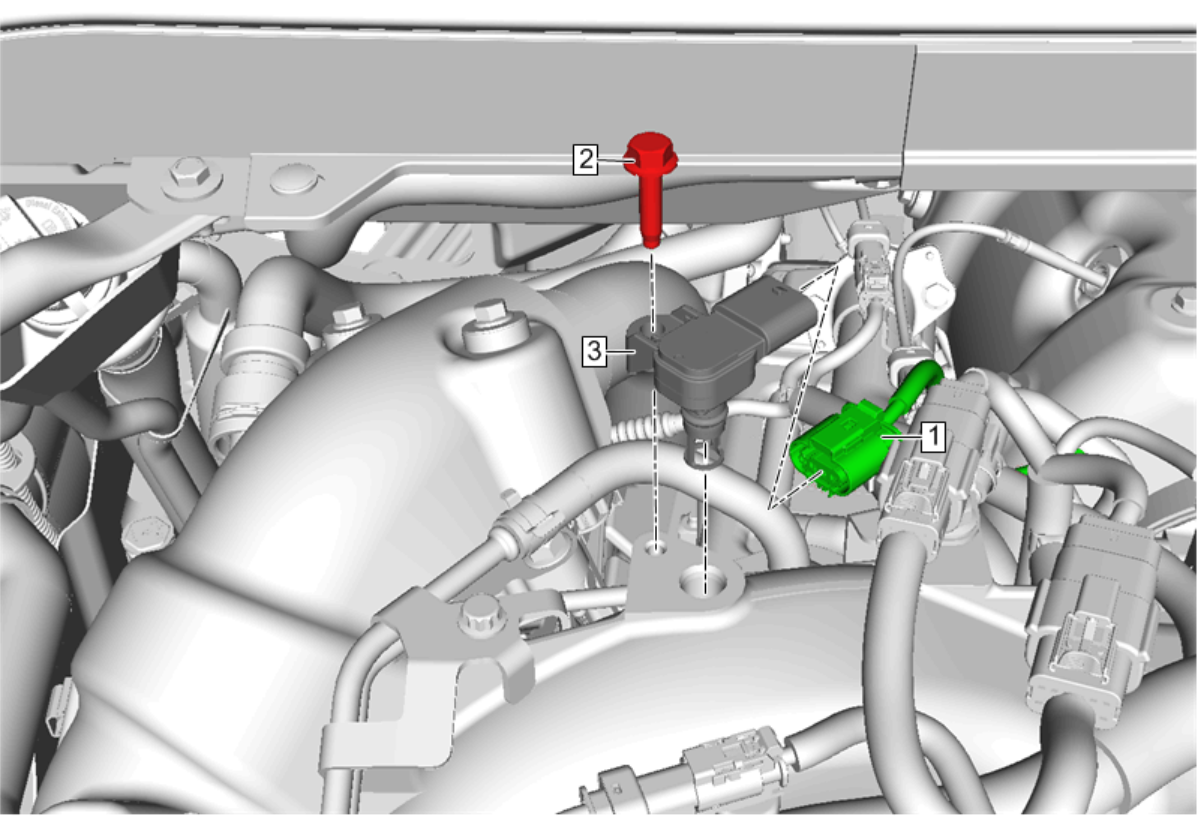
- Disconnect the intake air pressure and temperature sensor electrical connector (1).
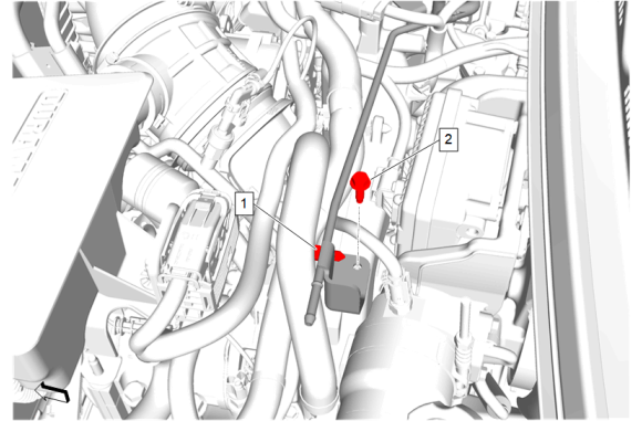
- Engine Wiring Harness Retainer(1)@Engine Coolant Air Bleed Pipe»Remove
- Engine Coolant Air Bleed Pipe Bolt(2)»Remove
- Engine Wiring Harness Retainer(2)@Engine Coolant Air Bleed Pipe»Remove
- Engine Coolant Air Bleed Pipe Bolt(1)»Remove
- Place absorbent cloths beneath the engine coolant air bleed pipe to capture any fluid loss.
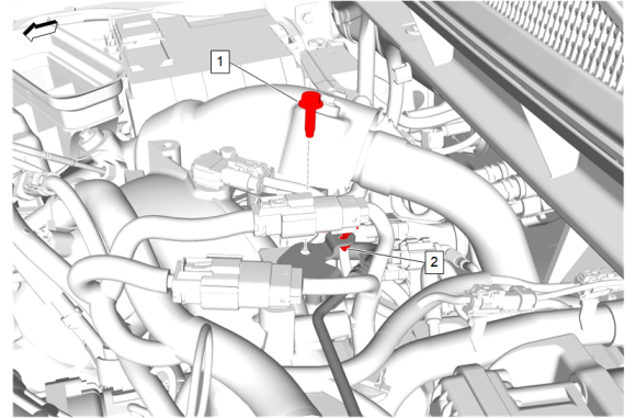
- Engine Coolant Air Bleed Hose Clamp(1)»Disengage—Hose Clamp Replacement Guidelines - Spring Type
- Engine Coolant Air Bleed Pipe(2)@Exhaust Gas Recirculation Manifold Cooling Feed Pipe»Remove
- Engine Coolant Air Bleed Pipe(2)»Reposition
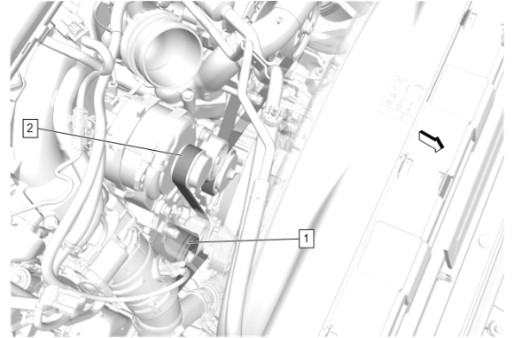
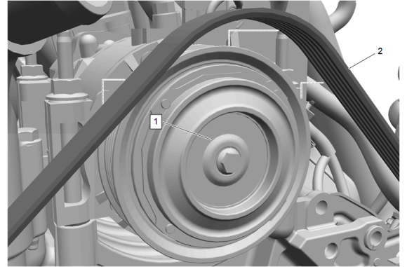
- Rotate the drive belt tensioner (1) counterclockwise and remove the accessory drive primary belt (2) from the generator pulley.
- Accessory Drive Primary Belt(2)@Air Conditioning Compressor(1)»Reposition
- Slowly release the drive belt tensioner.
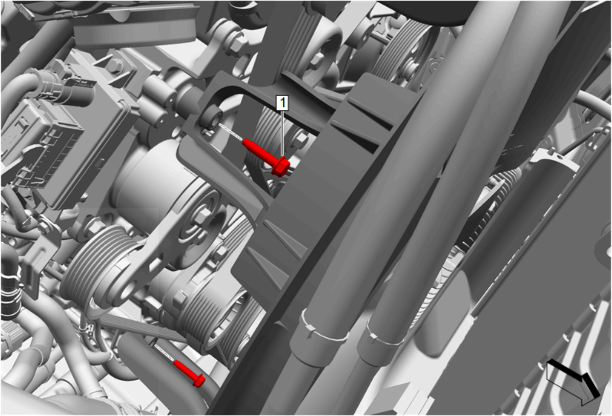
- Engine Coolant Fan Bracket Bolt- Right Side(1)»Remove
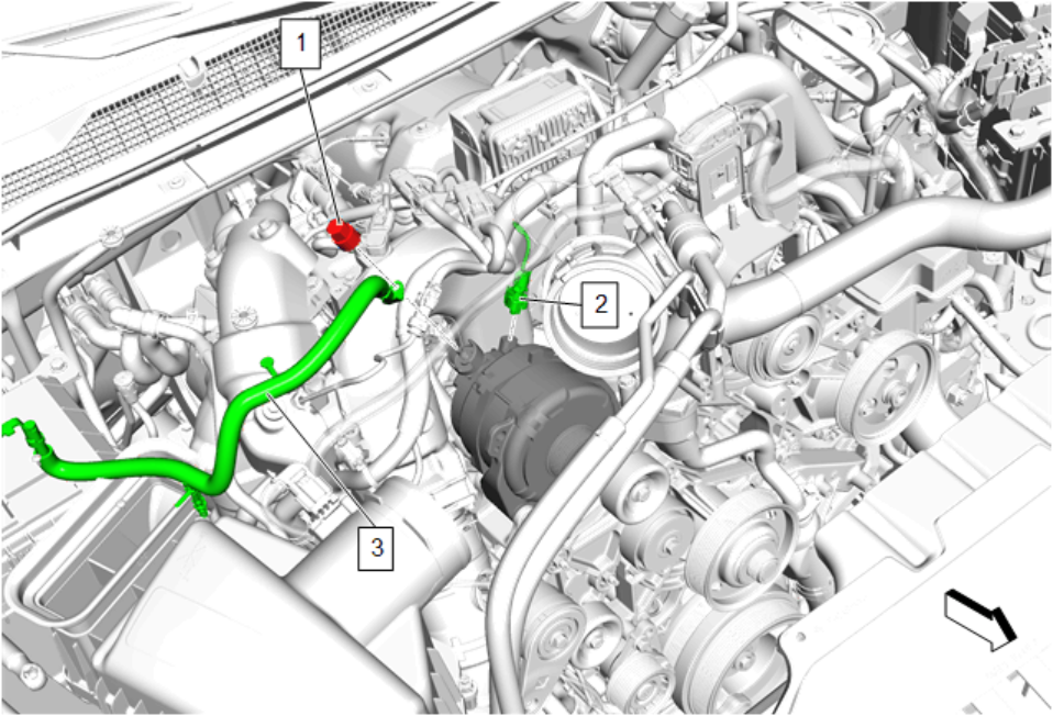
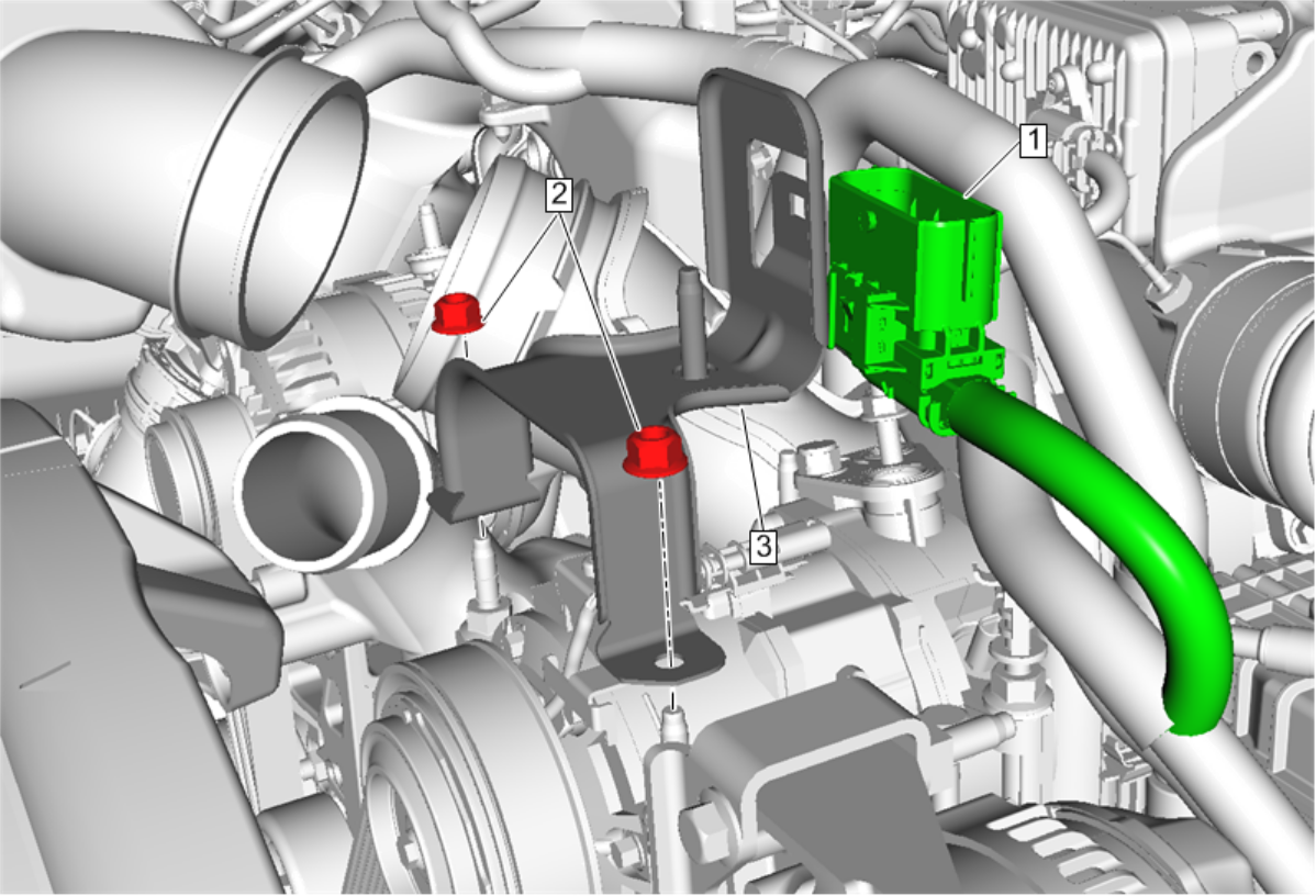
- Battery Positive Cable Nut(1)»Remove
- Generator Battery Jumper Cable(3)»Remove
- Electrical Connector(2)»Disconnect
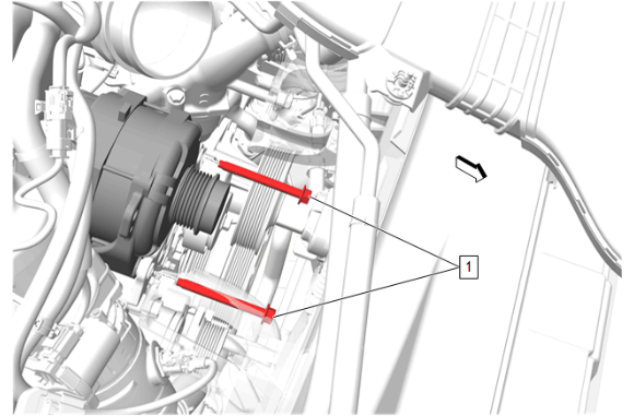
- Reposition the engine coolant fan rear shroud enough to remove the 2 generator bolts (1).
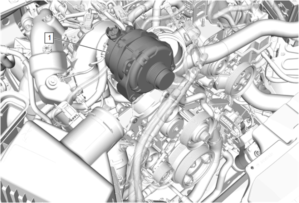
- Generator(1)»Remove
- Air Cleaner Resonator Nut(2)»Remove[2x]
- Intake Manifold Bracket(3)»Reposition
- Remove wiring harness retainer from the air conditioning compressor and condenser hose (2).
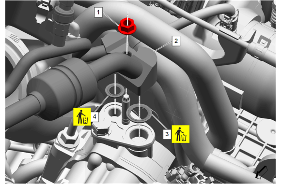
- Air Conditioning Compressor and Condenser Hose Nut(1)@Air Conditioning Compressor»Remove
- Air Conditioning Compressor and Condenser Hose(2)@Air Conditioning Compressor»Remove and position aside
- Air Conditioning Compressor and Condenser Hose Seal - Large (3)»Remove and DISCARD
- Air Conditioning Compressor and Condenser Hose Seal - Small (4)»Remove and DISCARD
- Disconnect the electrical connectors.[2x]
- Engine Wiring Harness Retainer@Air Conditioning Compressor Stud(1)»Remove
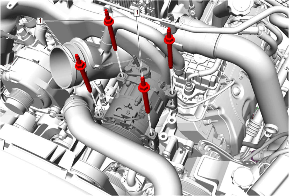
- Air Conditioning Compressor Stud(1)»Remove[4x]
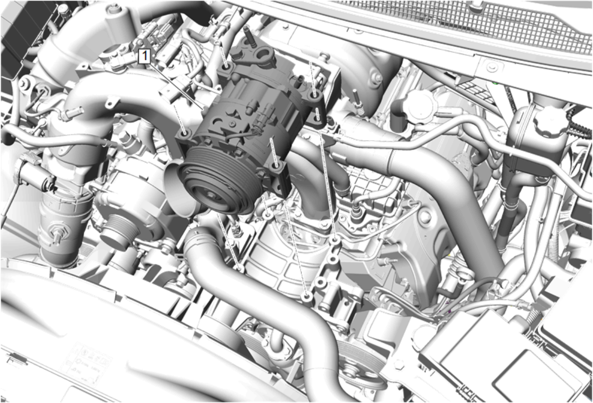
- Air Conditioning Compressor(1)»Remove
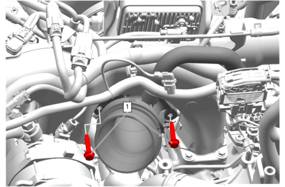
- Turbocharger Air Inlet Adapter Bolt(1)@Compressor Air Intake Turbocharger»Remove[2x]
- Turbocharger Air Inlet Adapter(1)@Compressor Air Intake Turbocharger»Remove and position aside
- Turbocharger Air Inlet Adapter Seal(2)»Remove and DISCARD
- Disconnect all electrical connectors and remove all wiring harness retainers as necessary for removal of the upper intake manifold.
- Upper Intake Manifold Bolt(1)»Remove[8x]
- Upper Intake Manifold(2)»Remove
- Upper Intake Manifold Seal(3)»Remove and DISCARD[2x]
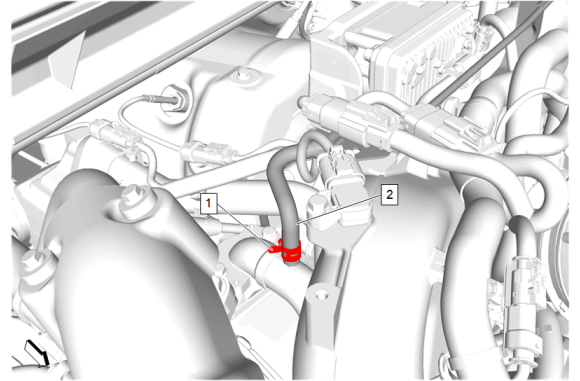
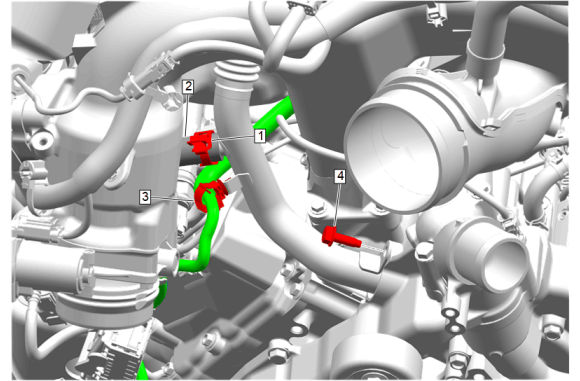
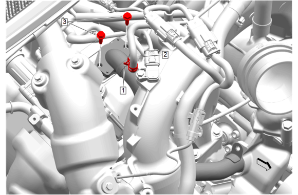
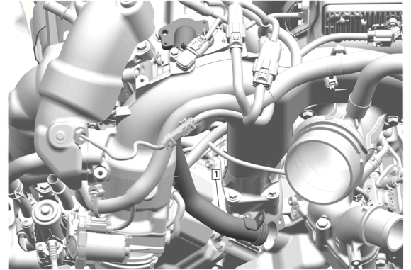
- Exhaust Gas Recirculation Valve Cooling Feed Hose Clamp(1)»Disengage—Hose Clamp Replacement Guidelines - Spring Type
- Exhaust Gas Recirculation Valve Cooling Feed Hose(2)@Exhaust Gas Recirculation Manifold Cooling Feed Pipe»Remove
- Wiring Harness Retainer(3)@Exhaust Gas Recirculation Manifold Cooling Feed Pipe»Remove
- Exhaust Gas Recirculation Manifold Cooling Feed Pipe Bolt(4)»Remove
- Exhaust Gas Recirculation Manifold Cooling Feed Pipe Bolt(3)»Remove[2x]
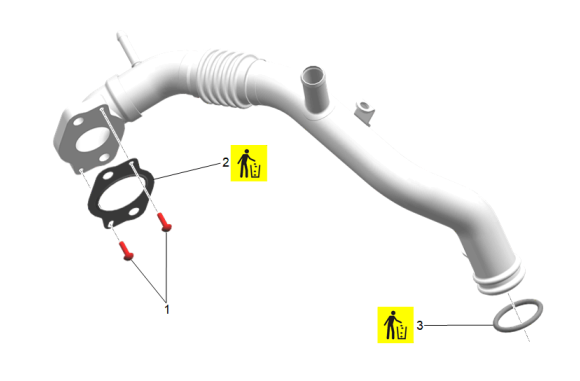
- Exhaust Gas Recirculation Manifold Cooling Feed Pipe(1)»Remove
- Retainer(1)»Remove[2x]
- Exhaust Gas Recirculation Cooler Pipe Gasket(2)»Remove and DISCARD
- Exhaust Gas Recirculation Coolant Feed Pipe Seal(3)»Remove and DISCARD
- Exhaust Gas Recirculation Valve Pipe Heat Shield Bolt(1)»Remove[3x]
- Exhaust Gas Recirculation Pipe Shield(2)»Remove
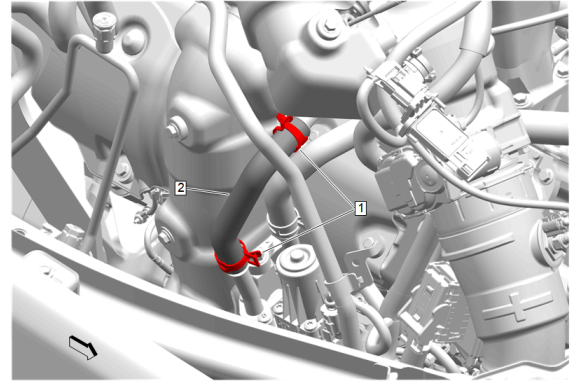
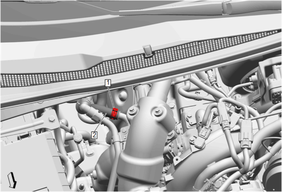
- Exhaust Gas Recirculation Valve Cooling Feed Hose Clamp(1)@Exhaust Gas Recirculation Valve Cooler Bypass Valve»Disengage—Hose Clamp Replacement Guidelines - Spring Type
- Exhaust Gas Recirculation Cooler Water Bypass Inlet Hose(2)@Exhaust Gas Recirculation Valve Cooler Bypass Valve»Remove
- Heater Inlet Hose Clamp(1)»Disengage—Hose Clamp Replacement Guidelines - Spring Type
- Heater Inlet Hose(2)@Exhaust Gas Recirculation Valve Cooler Bypass Valve»Remove
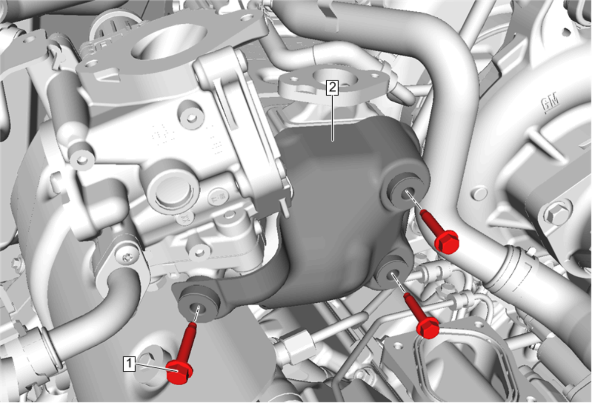
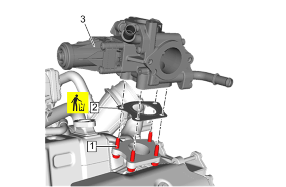
- Exhaust Gas Recirculation Cooler Bypass Valve Bolt(1)»Remove[4x]
- Exhaust Gas Recirculation Valve Cooler Bypass Valve(3)»Remove
- Exhaust Gas Recirculation Valve Cooler Bypass Valve Gasket(2)»Remove and DISCARD
Note: Left side shown, right side similar.
Note: Some components not shown for graphic clarity.
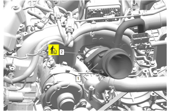
Note: If removing the turbocharger air inlet adapter (1) to service other components, simply reposition out of the way. Do NOT destroy the tamper-proof band clamps as they are not serviceable.
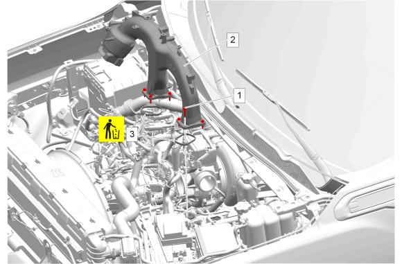
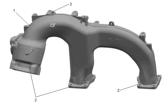
- Clean the upper intake manifold (1).
- Clean and inspect all mating surfaces.(2)
- Inspect the upper intake manifold (1) for damage.
- Replace the upper intake manifold (1) if any damage is found.
- Clean the exhaust gas recirculation valve cooler bypass valve (1).
- Inspect the exhaust gas recirculation valve cooler bypass valve (1).
- Replace the exhaust gas recirculation valve cooler bypass valve (1) if any damage is found.
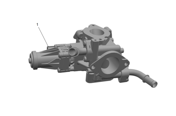
- Exhaust Gas Recirculation Valve Cooler Bypass Valve Gasket(2)»Install NEW
- Exhaust Gas Recirculation Valve Cooler Bypass Valve(3)»Install
- Exhaust Gas Recirculation Cooler Bypass Valve Bolt(1)»Install and tighten[4x]—Fastener Specifications
- Exhaust Gas Recirculation Cooler Water Bypass Inlet Hose(2)@Exhaust Gas Recirculation Valve Cooler Bypass Valve»Install
- Exhaust Gas Recirculation Valve Cooling Feed Hose Clamp(1)@Exhaust Gas Recirculation Valve Cooler Bypass Valve»Engage—Hose Clamp Replacement Guidelines - Spring Type
- Heater Inlet Hose(2)»Install
- Heater Inlet Hose Clamp(1)»Engage—Hose Clamp Replacement Guidelines - Spring Type
- Exhaust Gas Recirculation Pipe Shield(2)»Install
- Exhaust Gas Recirculation Valve Pipe Heat Shield Bolt(1)»Install and tighten[3x]—Fastener Specifications
- Exhaust Gas Recirculation Coolant Feed Pipe Seal(3)»Install NEW
- Exhaust Gas Recirculation Cooler Pipe Gasket(2)»Install NEW
- Retainer(1)»Install[2x]
- Exhaust Gas Recirculation Manifold Cooling Feed Pipe(1)»Install
- Exhaust Gas Recirculation Manifold Cooling Feed Pipe Bolt(3)»Install and tighten[2x]—Fastener Specifications
- Exhaust Gas Recirculation Manifold Cooling Feed Pipe Bolt(4)»Install and tighten—Fastener Specifications
- Wiring Harness Retainer(3)@Exhaust Gas Recirculation Manifold Cooling Feed Pipe»Install
- Exhaust Gas Recirculation Valve Cooling Feed Hose(2)@Exhaust Gas Recirculation Manifold Cooling Feed Pipe»Install
- Exhaust Gas Recirculation Valve Cooling Feed Hose Clamp(1)»Engage—Hose Clamp Replacement Guidelines - Spring Type
- Upper Intake Manifold Seal(3)»Install NEW[2x]
- Upper Intake Manifold(2)»Install
- Upper Intake Manifold Bolt(1)»Install and tighten in sequence[8x]—Fastener Specifications
- Connect all electrical connectors and install all wiring harness retainers as necessary for installation of the upper intake manifold.
- Turbocharger Air Inlet Adapter Seal(2)»Install NEW
- Turbocharger Air Inlet Adapter(1)@Compressor Air Intake Turbocharger»Install
- Turbocharger Air Inlet Adapter Bolt(1)@Compressor Air Intake Turbocharger»Install and tighten[2x]—Fastener Specifications
- Air Conditioning Compressor(1)»Install
- Air Conditioning Compressor Stud(1)»Install and tighten[4x]—Fastener Specifications
- Engine Wiring Harness Retainer@Air Conditioning Compressor Stud(1)»Install
- Connect the electrical connectors.[2x]
- Air Conditioning Compressor and Condenser Hose Seal - Large(3)»Install NEW
- Air Conditioning Compressor and Condenser Hose Seal - Small(4)»Install NEW
- Air Conditioning Compressor and Condenser Hose(2)@Air Conditioning Compressor»Install
- Air Conditioning Compressor and Condenser Hose Nut(1)@Air Conditioning Compressor»Install and tighten—Fastener Specifications
- Attach the wiring harness retainer to the air conditioning compressor and condenser hose (2).
- Intake Manifold Bracket(3)»Install
- Air Cleaner Resonator Nut(2)»Install and tighten[2x]—Fastener Specifications
- Generator(1)»Install
- Generator Bolt(1)»Install and tighten[2x]—Fastener Specifications
- Rotate the drive belt tensioner (1) counterclockwise and install the accessory drive primary belt (2) onto the generator pulley.
- Accessory Drive Primary Belt(2)@Air Conditioning Compressor(1)»Install
- Slowly release the drive belt tensioner.
- Inspect the accessory drive primary belt (2) for correct alignment.
- Engine Coolant Fan Bracket Bolt- Right Side(1)»Install and tighten—Fastener Specifications
- Generator Battery Jumper Cable(3)»Install
- Battery Positive Cable Nut(1)@Generator»Install and tighten—Fastener Specifications
- Electrical Connector(2)»Connect
- Engine Coolant Air Bleed Pipe(2)@Exhaust Gas Recirculation Manifold Cooling Feed Pipe»Install
- Engine Coolant Air Bleed Hose Clamp(1)»Engage—Hose Clamp Replacement Guidelines - Spring Type
- Remove the absorbent cloths from beneath the engine coolant air bleed pipe and wipe up any spillage.
- Engine Coolant Air Bleed Pipe Bolt(1)»Install and tighten—Fastener Specifications
- Engine Wiring Harness Retainer(2)@Engine Coolant Air Bleed Pipe»Install
- Engine Coolant Air Bleed Pipe Bolt(2)»Install and tighten—Fastener Specifications
- Engine Wiring Harness Retainer(1)@Engine Coolant Air Bleed Pipe»Install
- Connect the intake air pressure and temperature sensor electrical connector (1).
- Exhaust Gas Recirculation Pipe Gasket(2)»Install NEW[3x]
- Retainer(3)»Install[6x]
- Exhaust Gas Recirculation Pipe(1)»Install
- If a NEW threaded component is being installed, loosen the adhesive using a metal pick or similar tool before proceeding. If threaded component is reused, prepare the threaded component using the following steps:
- Remove any loose cured adhesive from the external threads of the component using a lint free cloth.
- Thread the cleaned component into the internal mating threads and remove to loosen trapped cured adhesive.
- Apply thread locking adhesive to the external threads of the component.Adhesives, Fluids, Lubricants, and Sealers
- Ensure there are no gaps in the thread locking adhesive once applied to the component.
- Exhaust Gas Recirculation Pipe Bolt(1)»Install and tighten[2x]—Fastener Specifications
- If a NEW threaded component is being installed, loosen the adhesive using a metal pick or similar tool before proceeding. If threaded component is reused, prepare the threaded component using the following steps:
- Remove any loose cured adhesive from the external threads of the component using a lint free cloth.
- Thread the cleaned component into the internal mating threads and remove to loosen trapped cured adhesive.
- Apply thread locking adhesive to the external threads of the component.Adhesives, Fluids, Lubricants, and Sealers
- Ensure there are no gaps in the thread locking adhesive once applied to the component.
- Exhaust Gas Recirculation Pipe Bolt(1)»Install and tighten[2x]—Fastener Specifications
- If a NEW threaded component is being installed, loosen the adhesive using a metal pick or similar tool before proceeding. If threaded component is reused, prepare the threaded component using the following steps:
- Remove any loose cured adhesive from the external threads of the component using a lint free cloth.
- Thread the cleaned component into the internal mating threads and remove to loosen trapped cured adhesive.
- Apply thread locking adhesive to the external threads of the component.Adhesives, Fluids, Lubricants, and Sealers
- Ensure there are no gaps in the thread locking adhesive once applied to the component.
- Exhaust Gas Recirculation Pipe Bolt(1)»Install and tighten[2x]—Fastener Specifications
- Exhaust Gas Recirculation Pipe Gasket(3)»Install NEW[2x]
- Retainer(2)»Install[4x]
- Exhaust Gas Recirculation Pipe(1)»Install
- If a NEW threaded component is being installed, loosen the adhesive using a metal pick or similar tool before proceeding. If threaded component is reused, prepare the threaded component using the following steps:
- Remove any loose cured adhesive from the external threads of the component using a lint free cloth.
- Thread the cleaned component into the internal mating threads and remove to loosen trapped cured adhesive.
- Apply thread locking adhesive to the external threads of the component.Adhesives, Fluids, Lubricants, and Sealers
- Ensure there are no gaps in the thread locking adhesive once applied to the component.
- Exhaust Gas Recirculation Pipe Bolt(1, 2)»Install and tighten[4x]—Fastener Specifications
- Exhaust Gas Recirculation Pipe Shield(1)»Install
- Exhaust Gas Recirculation Valve Pipe Heat Shield Bolt(1)»Install and tighten—Fastener Specifications
- Radiator Outlet Hose Bracket Bolt(1)»Install and tighten—Fastener Specifications
- Exhaust Gas Recirculation Valve Pipe Heat Shield Bolt(1)»Install and tighten[2x]—Fastener Specifications
- Front Wheelhouse Liner-Right Side(3)»Install—Front Wheelhouse Liner Replacement
- Connect the exhaust gas recirculation cooler temperature sensor (1) electrical connector.
- Exhaust Gas Recirculation Pipe Shield(1)»Install
- Exhaust Gas Recirculation Valve Pipe Heat Shield Bolt(1)»Install and tighten[3x]—Fastener Specifications
- Connect the throttle body electrical connector.
- Charge Air Cooler Outlet Air Hose(2)»Install
- Retainer Spring(1)»Engaged
- Connect the charge air temperature sensor electrical connector.
- Install the air cleaner and air cleaner outlet resonator assembly (1).
- Turbocharger Outlet Duct Connector Clamp(1)»Tighten—Fastener Specifications
- Air Cleaner Resonator Nut(2)»Install and tighten—Fastener Specifications
- Electrical Connector(2)»Connect
- Air Cleaner Nut(1)»Install and tighten—Fastener Specifications
- Secure the wiring harness retainers to the air cleaner assembly.
- Connect the negative battery cable.Battery Negative Cable Disconnection and Connection
- Fill the cooling system to the proper level.Cooling System Draining and Filling
- Recharge the refrigerant.Refrigerant Recovery and Recharging
- Start the engine and check for coolant leaks.
- Inspect for refrigerant leaks.Leak Testing
- Listen for whistling at the charge air cooler outlet air hose quick connect located at the charge air cooler.
Caution: Refer to Fastener Caution.
Note: The exhaust gas recirculation cooler pipe gasket (2) is attached to the exhaust gas recirculation manifold cooling feed pipe with retainers (pins) to aid in factory installation. These retainers will help ensure proper gasket alignment and prevent leaks. When servicing the exhaust gas recirculation manifold cooling feed pipe, remove the retainers and install a NEW gasket. Re-install the retainers with a soft-blow hammer.
Note: If removing the turbocharger air inlet adapter (1) to service other components, simply reposition out of the way. Do NOT destroy the tamper-proof band clamps as they are not serviceable.
Caution: Refer to Air Conditioning Sealing Washers Oil or Lubricant Exposure Caution.
Note: The 3 exhaust gas recirculation pipe gaskets (2) are attached to the exhaust gas recirculation pipe (1) with pins (3) to aid in factory installation. The gaskets ARE serviceable and ARE one-time use ONLY. Reinstall the OLD pins with a soft-blow hammer. The pins will help ensure proper gasket alignment and prevent leaks.
Note: The exhaust gas recirculation pipe gaskets (3) are attached to the exhaust gas recirculation pipe with pins (2) to aid in factory installation. The gaskets ARE serviceable and ARE one-time use ONLY. Reinstall the OLD pins with a soft-blow hammer. The pins will help ensure proper gasket alignment and prevent leaks.
Note: Line the notch of the charge air cooler outlet air hose to the tab on the throttle body assembly.